Mat foundations also are known as raft foundations, is a thick concrete slab placed on the ground as the foundation of the structure. Mat foundations are constructed on various occasions such as building construction, bridge construction, tower construction, etc.
If we are dealing with the shallow foundations, the last option of the shallow foundation is a raft foundation.
With the increase of the axial loads on the structure or due to the poor ground conditions, the area of the footings (isolated, combined, strip footing, etc) need to be increased.
The increase of the dimensions of the footings further and further, cause overlapping the stress bulbs each other create the weak zone. In this backdrop, we select the raft foundations.
What is a Mat Foundation?
Mat foundation is always not a flat plate place on the ground as the superstructure support. There are a variety of designs based on the application of loads.
Smaller the loads applied on the mat foundation, we construct a flat plate. However, with the increase of the loads, different methods that discuss in this article are introduced to enhance the stiffness of the slab.
Further, we could use raft foundations to support the buildings up to about 10 floors.
In addition, an increase in the axial loads ensures a higher cost for construction work. It could even exceed the construction of a pile foundations beyond a certain level.
Types of Mat Foundation
The categorization of the mat foundations is made based on the modifications made to the flat plate.
Additionally to the raft is made to improve the flexural stiffness of the foundation.
The depth of the raft foundation is manly increased at column positions to carry the high bending moments and shear forces.
The following categorization discussed in the article Types of Foundations could be referred for more detailed information about them.
- Flat Plate
A thick concrete slab cast as the foundation on the soil is a flat raft.
There are no projections to stiffen the mat foundation other than the concrete shear walls.
- Flat Plate Foundation Thicknened under the Column
The increase of column axial loads, lead to increasing the bending and shear reinforcements.
It leads to an increase in the cost of construction. Further, beyond a certain level, we have to increase the thickness of the mat foundation.
If we increase the thickness of the whole mat foundation, it will not be an economical way to handle it.
Thus, we increase the thickness of the mat foundation below the columns. Since the projection is below the flat plate, construction could be difficult.
Placing the reinforcement, waterproofing, etc could not be that easy.
- Flat Plate Foundation Thicknened above the frat at column
The projection above the flat plate is also the same as the projection below the plate.
Constructing the projection from the raft above its surface is much easy. However, we can only do this if we are not using the raft slab or the remaining spacing is sufficient for the purpose to be used.
- Beam and Slab Raft foundation
Further increase of the column axial load cannot be born by the flat plate or projections from the flat plate. Beams are provided to stiffen the foundation.
The introduction of beams reduces the raft slab thickness considerably.
- Cellular Raft foundations
One step development form the beam raft is the cellular raft foundation. In this type of foundation, we place the top slab too.
It further increases the stiffness of the mat foundation.
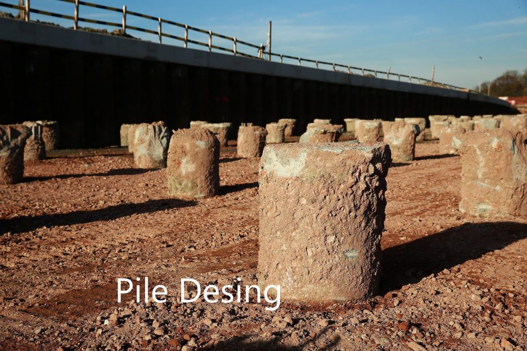
- Pile Raft foundations
Plie raft foundations are constructed in high rise buildings, in situations where the pile cannot be socketed in the rock and when end bearing of the pile is not sufficient, etc.
The design and construction of the pile raft foundation is a complex process.
Initially, the pile takes the load, and then it starts sharing with the raft foundation.
Once the piles are fully mobilized, then raft starts taking the load fully. Finally, the raft takes the whole load.
The following figure indicates the load vs settlement curve.

The article published on the pile raft foundation could be referred for more information.
The following figure indicates the different types of raft foundations available to apply for designs.

The selection of the type of mat foundation is made based on the applied load on the foundation system.
Design of Mat Foundation
Mainly there are two methods to design the raft foundations.
- Conventional methods – Use manual calculations and charts
- Finite element analysis methods – Use a computer package to solve the design
Design of Mat Foundations with Conventional Rigid Method
The following steps can be followed when designing the mat foundation from the conventional rigid method.
- Calculate the total applied load into the mat foundation
- Calculate the pressure under each column considering the eccentricity of the loading. Axial stress and bending stress due to the eccentricity of the load center are considered to determine the pressure under each column.
- Check whether the net allowable press is grater than applied pressure.
- Then the mat is divided into the strips based on its arrangement.
- Determine the bending moment and shear forces.
- Determine the effective depth of the footing. It could be done based on the diagonal tension shear near various columns.
- Form the bending moment diagrams calculated above, determine the positive and negative bending moments per unit width.
- Calculate the reinforcement area per unit width of the section
In addition to this procedure, there are other methods such as approximate flexible method to analyze and design the raft foundations.
Finite Element Analysis Methods
The finite element analysis method is the consideration of the soil flexible behavior in the structural analysis. In this method the soil is model and its behavior is incorporated into the analysis and design.
There are different methods to model the soil.
We can model the soil under the foundation with its material properties. Softwares like plaxis could be used for this purpose. It is very important to select the correct material model for the soil in this type of analysis. If we are not considering the correct idealization, we will end up with the wrong answers.
In addition, we could use software like SAFE foundation analysis and design to get the bending moments and shear forces.
Soil can be model as the area springs. The area springs can be calculated as specified in the Bowels Foundations analysis and design book.
The area spring is the subgrade reaction of the soil. There are many methods to calculate the subgrade reaction. In this article, we are discussing the simplest method specified in the book Bowels Foundation Analysis and Design.
Area Spring = SF x 40 x BC – for 25mm settlement of raft foundation
Where, SF – safety factor considered to calculate the allowable bearing capacity and BC is the allowable bearing capacity.
The above equation is for a settlement of 25mm in the raft foundation. The variation beyond this value could give wrong answers.
Therefore, based on the specified settlement in the geotechnical investigation report to determine the allowable bearing capacity or based on the calculated settlement, the above equation shall be modified.
Area Spring = SF x (1000/settleemnt ) x BC
Once we calculate the soil area sprigs or soil subgrade reaction, it can be applied to the computer model created with suitable software.
After applying the loads at column positions, analysis of the foundation can be carried out. Then we can find the bending moment and shear forces.
Reinforcement calculation shall be done as per the analysis results.
Special note on Analysis and Desing of Raft Foundations
- It is advisable to use computer aid software to analyze and design the mat foundations.
- Modeling and idealization of the actual behavior of the foundation shall be done very carefully and with much care.
- Soil could be model with area springs. It is the subgrade reaction. We define the subgrade reaction in the software and assign it to the computer model.
- Susbgrate reaction could be estimated based on the different methods available. It could be based on the SPT value, test results, bearing capacity of the soil, or using any method.
- Foundation could be modeled together with the superstructure to combined the behavior of the superstructure and foundation. The deflection of the foundation could affect the superstructure and the behavior of the superstructure can be incorporated in the foundation deformations.
- Further, the foundation could also be a model without a superstructure. The column load could be applied to the model directly. Shear walls could be considered to incorporate in the model.
- Mat foundation shall be designed for bending and shear forces.
- Foundation should be checked for vertical line shear and punching shear. The punching shear perimeter could be decided as per the relevant standard that the design is carried out. The article on punching shear design could be referred for design and for the definition of the shear perimeter.
- Special attention shall be made when designing for shear. Shear link requirement shall be checked and shear links shall be provided where required as calculations.
- Pile Raft analysis design is a complex process and it shall be done with the relevant literature published.
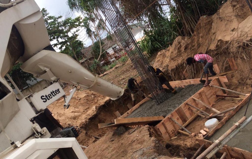
Construction of Mat Foundation
Construction of the mat foundation is also done with much attention and with due care on quality control and quality assurance.
Let’s discuss the construction process one by one.
- Excavation for Mat Foundations
Excavation and excavation supporting the system shall be decided before starting the construction. Depending on the nature of the construction and depth of the construction, the type of supporting system for excavation shall be decided.
The article excavation for foundation could be referred for more on design can construction aspects of excavation systems.
Further, articles design of excavation support systems and sheet pile retaining wall could be referred for worked examples on earth retaining systems.
- Waterproofing
In general, all the mat foundations are waterproofed. Waterproofing of all the raft foundations are done as mostly they are constructed below the finished ground level.
Providing a waterproofing membrane protects the foundation from getting wet or damping. In addition, water movement through the concrete also avoided being the waterproofing.
The article on the different types of waterproofing details used in the construction could be referred to as knowing the arrangement of waterproofing membranes.
- Waterstop
There are construction joints, movement joints, expansion joints, etc in the raft foundation. They shall be seal to avoid the movement of water through the joint.
The articles construction joints and types of concrete joints could be referred for more information for joint details and methods of treating the joint.
Waterstops are provided at construction joints and movement joints. Type of the joint changes the type of water stop to be provided.
In construction joints, we usually provided waterstop at the center of the raft. (Refer the article Waterproofing for the typical detail). Mild steel or PVC type waterstops are usually provided in these types of joints.
Surface type water bars are provided in the movement and expansion joints. (Refer the article Waterproofing for the typical detail)
In addition, further information could be referred from the article Waterstop.
- Reinforcements
Mainly there are two types of reinforcement that can be observed in a raft foundation.
They are bending reinforcements and shear reinforcement.
Bending reinforcements are tied as usually and shear reinforcements are placed at column mainly as per the requirements for shear. Shear links shall be as per the design requirements. The spread of the shear links in either direction of the column shall be as per the design requirements.
- Number of Pours
Depending on the nature of construction and as per the design requirements concrete pouring is done is several pours.
It is not a must to have several pours but it can be concrete in a single pore if the dimension of the mat foundation is smaller and there are adequate resources such as human resources and material resources.
In a large mat foundation, the number of pours is decided based on the contractor’s capacity to supply and place the concrete.
In addition, the thermal effects are considered when deciding the sequence of pouring of concrete. Initially, the sequence that could follow to concrete is decided in such a manner that it minimizes the thermal restrain by another pour. However, we can not avoid it always. We have to design for it.
Further, the poring sequence is planned for every single pour to avoid the cold joint with the pour. Based on the setting time, the concrete needs to poured before it starting the setting.
- Temperature Control
Rise of the temperature of the concrete, higher temperature gradient, and the difference of temperature between the core and surface are key factors to be considered in temperature control.
As a practice, we maintain the maximum rise of the temperature of concrete due to the heat of hydration to 70 Celcius to avoid delayed ettringite formation.
However, the addition of the fly ash lifts this margin even up to 80 Celcius or more. The maximum temperature highly depends on the type of cement too.
Therefore, it is always advisable to maintain the temperature around 70 Celcius or lesser as we cannot observe what happens within the concrete.
Mockup tests are carried out the check the rise of the temperature in the concrete due to the heat of hydration. In addition, it provides other advantage such as deciding the thickness and type of materials to be used as formwork.
The same material used in the mockup test and if the rise of the temperature is acceptable, shall be used in the construction too. No changes shall be made to the material and the material thickness.
The addition of the fly ash to the concrete acts as a filler and it reduces the cement content. Further, it reduces the rise of the temperature in the hydration process.
It is comment practices to maintain the addition of fly ash to maintain in the range of about 20% – 35%.
In addition, the use of fly ash in concrete improves the workability of concrete.
The other methods liming temperature of concrete are listed below.
-
- Limit the placing temperature. It is common practice to limit the placing temperature to 30 Celcius. However, lowering further will be required to limit the rise of the temperature.
- Add ice of chilled water to lower the rise of temperature.
- Pour the concrete at night
- Add fly ash
- Coll the aggregates
- Use low heat generating cement
- Coll the concrete from the pipes embedded in the concrete.
Similar methods could be adopted to control the rise of the temperature of the concrete. If controlled, we could be above to avoid the formation of delayed ettringite due to the rise of the heat of hydration, thermal cracks in the concrete due to temperature difference, and high-temperature gradient.