Looking for the design of excavation support systems?
The timber shoring system is a more commonly adopted method to protect the excavated embankment in construction as it is more economical when compared with other techniques. However, there are limitations like smaller retaining heights that its application was limited to a certain extent.
In this article, we discuss the analyzing, design and detailing of the shoring system. The shoring system is proposed to protect the excavated embankments, and it is mainly required to minimize the impact on the adjoining structures and slope failures. The design procedure is expressed with a design calculation.
Design of Excavation Support Systems: Worked Example
Assumptions and Parameters
The following assumptions and design data were considered in the analysis and design.
- Height to the water table from finished ground Level 2m
- Density of concrete 25 kN/m3
- Density of soil 18 kN/m3
- Density of saturated soil 20 kN/m3
- Density of submerged soil 10 kN/ m3
- Density of the water 10 kN/ m3
- Soil friction angle 300 (average friction angle is considered for Borehole 01. Since the friction angle of some layers is zero, the above values, is assumed.
- Width of the steel section 150mm
Structural Arrangement of Shoring System
Steel sections (H iron) are spaced at a spacing of 1.2m to have a depth of excavation of 4m. Steel plates will be installed in between the H iron bars to retain the earth.
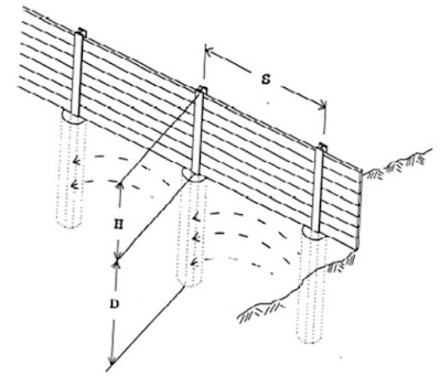
Figure 01: Arrangement of the Shoring System
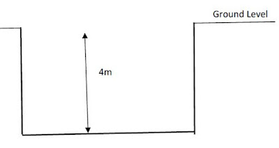
Figure 02 : Typical Excavation Detail
Structural Analysis of Shoring System – excavation support systems
Structural analysis of the shoring system is done as per the guidelines are given in the California Trenching and Shoring Manual. The average angle of friction is considered as 300 in this analysis. Since the angle of friction is varying, average values are assumed in the design.
When the effective width is 1.2m above the dredging line, it becomes 150mm (width of the H iron) below the dredging line.
Therefore, the conversion method is considered to find the equivalent effective width.
Further, the arching effect is considered in this analysis to enhance the load resisting capacity of the H iron below the dredging line. Figure 03 indicates the pressure distribution of the shoring system.
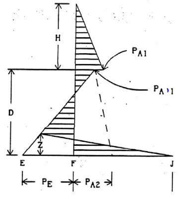
Figure 03 : Pressure Distribution
Surcharged load and the water pressure above the dredging line is not considered in the calculation as this calculation is done to check whether this system is applicable for proposed excavation depths.
Following factors were considered in the design
Adjustment for arching effect
Arching Capability = 0.08φ (≤ 3.00)
Adjustment for pile width = (effective width) x 0.08φ (≤ 1.00)
Arching factor (f) = 0.08φ (effective pile width)/ (pile spacing) ≤ 1.0)
Arching factor (f) = 0.08φ (effective pile width)/ (pile spacing) ≤ 1.0
Calculations
Following the calculation indicates the method of evaluating the required embedment depth of the steel section to bear the active pressure excreted by the sole above the dredging line.
Calculation of Design Parameters
Soil friction angle = 300
Ka = (1-Sin φ ) / 1+Sin φ ) = (1-Sin 30 ) / 1+Sin 30 ) = 0.333
Kp = (1+Sin φ ) / 1-Sin φ ) = (1+Sin 30) / 1-Sin 30 ) = 3.000
Arching Capability = 0.08φ (≤ 3.00) = 0.08 x 30 = 2.4 < 3
Adjustment for pile width = (effective width) x 0.08φ (≤ 1.00) = 0.15 x 0.08 x 30 = 0.36 < 1
Arching factor (f) = 0.08φ (effective pile width)/ (pile spacing) ≤ 1.0 = 0.08 x 30 x 0.15 / 1.2 = 0.3
Submerged density of soil = γsat -γw = 20 –10 = 10 kN/m3
For all the notation referred herein shall be as shown in Figure 3 and Figure 3.
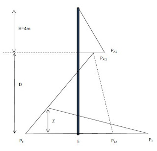
Figure 04 : Notations – Pressure Distribution