Analysis and Design of Concrete Retaining Wall
Concrete Retaining Wall Design
Firstly, we need to check the stability of the retaining wall. Overturning and sliding shall be checked before proceeding with the design. For more details about above checks click here.
In addition, we need to check the bearing under the foundation. If the wall is supported on soil, bearing pressure under the foundation of the wall shall be less than the allowable bearing capacity.
First of all, we need to analyze the retaining wall and find the bending moments and shear forces.
This can be done with an analysis software like SAP2000 or PROKON or any other software or by manual calculations. If there are variations such as steps in the retaining wall and we are more concentrated on stress variation of the wall, we may use software like SAP2000 or ANSIS.
Manual calculations can only be done for basic retaining walls that do not have many complications.
For example, cantilever retaining wall can be analysed by simplifying its behaviour.
We can assume the boundary condition “fixed” at the base to find the bending moments and shear forces of the wall. After finding wall forces, we can find the forces of the base of the wall.
The easiest method is to use the software at least to find the bending moments and shear forces.
Design Example
Consider a wall of height 3 m and width of base 2.3 m. Assume friction angle of 30 degrees and the water table is at 1 m above the base of the foundation. Wall thicknesses are considered as 0.3 m. This analysis is done from prokon software. Input details and analysis results are as follows.

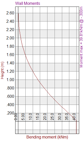

As per the above analysis, wall and base have maximum bending moments of 39.81 kNm and 46.85kNm respectively. Design of each element is carried out as per the guidelines are given in the BS 8110 Part 01 1997.
Design of wall
Cover to the reinforcement = 40 mm
Assume main bar diameter = 12 mm
Horizontal reinforcement dia = 10 mm
Thickness of the wall = 300 mm
Characteristic strength of concrete = 25
Characteristic strength of steel = 460 N/mm2
Effective depth = 300 – 40-10-12/2
= 244 mm
Bending Moment = 39.81 kNm
M/ bd2 = 0.669 N/mm2
100As/bd = 0.158
As = 385 mm2
Provide T10 at 200 mm centre to centre spacing. It should also be noted that this design does not cover the reinforcement requirements for cracking of concrete due to thermal effects.
Design of Base
Cover to the reinforcement = 40 mm
Assume main bar diameter = 12 mm
Horizontal reinforcement dia = 10 mm
Thickness of the wall = 300 mm
Characteristic strength of concrete = 25
Characteristic strength of steel = 460 N/mm2
Effective depth = 300 – 40-12/2
= 254 mm
Bending Moment = 46.85 kNm
M/ bd2 = 0.726 N/mm2
100As/bd = 0.172
As = 437 mm2
Provide T10 at 175 mm centre to centre spacing. It should also be noted that this design does not cover the reinforcement requirements for cracking of concrete due to thermal effects.