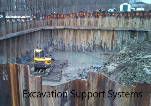
Sheet pile shoring is one of the more widely used excavations supporting methods in construction. Sheet pile shoring systems are cost-effective and can be installed in a short period of time with simple techniques.
In this article, we are focussing on the design of propped sheet pile shoring. Before that, let’s learn the background.
What is Shoring?
Shoring is a temporary supporting system of excavated earth until the construction is completed. It may be the construction of a basement, bridge pier, dame, or any other structure where we need some supports.
What are the Most Common Types of Shoring Methods?
- Soldier pile and lagging
- Sheet Pile Shoring
- Secant Pile Shoring
- Diaphram Wall
- Pressure/Chemical grouting
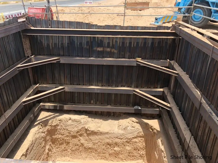
What is Sheet Pile Shoring?
Shoring is done using the sheet piles. Sheet piles are driven up to the hard layer or to a depth required by the design. Depth of the sheet piles shoring system is increased by 30% – 40% from design length as a safety margin.
Usually, when the depth of the sheet pile shoring increases, it is required to support laterally as it cannot withstand itself. However, when the depth is smaller, we may not be required to have supported.
For deep excavations, there may be more than one support for the sheet pile wall to retain the stable.
What is Propped Sheet Pile Shoring?
As discussed above, we cannot have a free-standing sheet pile wall without any support for any depth.
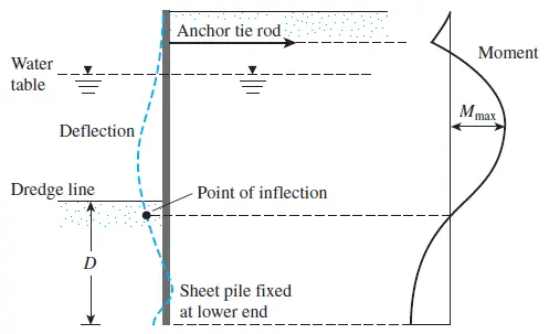
Lateral supports as indicated above figure need to be introduced at different levels. The number of support will be depending on the depth of the shoring.
Further, there may be struts supporting the wales runs along the sheet pile wall.
There are two design methods or anchoring method for sheet pile shoring systems
- Free earth support method
In this method, the bending moment of the sheet pile becomes zero at the end of the sheet pile.

- Fixed earth support method
In this method, there will be a hogging moment in the sheet pile wall. This cause due to the depth of the sheet pile within the soil.
In this article, we are concentrating on the design of propped sheet pile shoring. Further, the worked example is done for free Earth supported sheet pile wall.
Design of Propped Sheet Pile Shoring – Worked Example – Free Earth Supported
Design Date and Parameters
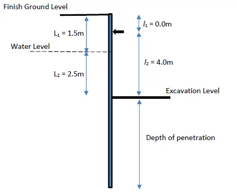
- Height to the water table from finished ground level = 1.5m
- Density of the soil 18 kN/m3
- Density of saturated soil 20 kN/m3
- Density of submerged soil 10 kN/m3
- Density of water 10 kN/m3
- Soil Friction angle 250
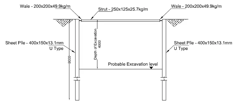
The following figure indicates the typical arrangement of the storage system to be designed.
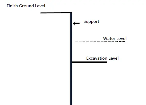
The general method available to analyze and design the sheet pile retaining walls is considered in the design to check the required length of the sheet piles.
Design procedure expressed in the book Principles of Foundation Engineering by Braja M. Das is referred for structural analysis and design.
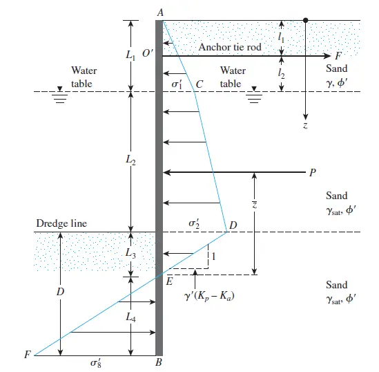
Figure 1 Pressure Variation Along the Sheet PIle Wall
The effect of the lateral support was considered with the lateral pressure generated from the water. The empty condition was taken into account in the calculation to find the maximum pressure on the sheet pile wall.
Analysis of the structure was done as per the procedure discussed above and based on the fee earth support method. The above figure indicates the earth pressure variation of the sheet pile shoring.
The following figure indicates the design parameters developed for this worked example as per the above figure.
Calculation of Earth Pressure Coefficients
Soil friction angle = 250
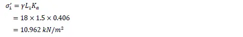
Ka = (1-Sin φ ) / 1+Sin φ ) = (1-Sin 25 ) / 1+Sin 25 ) = 0.406
Kp = (1+Sin φ ) / 1-Sin φ ) = (1+Sin 25) / 1-Sin 25 ) = 2.464
Calculate Depth of Penitration Beyond the Dreadging Line
All the notation in this worked example is as indicated in Figure 1 above.
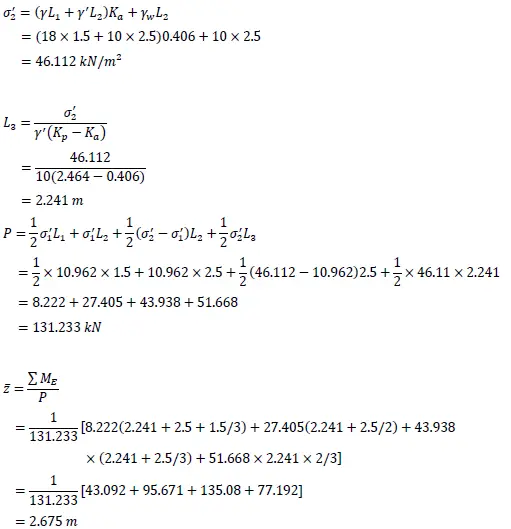
Taking moment about point O’ (Figure 1), the following equation can be derived.
![]()
The above equation can be written as follows to find L4.
![]()
Values of the A1 and A2 can be evaluated as follows.
where
![]()
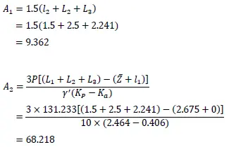
Thus, the above equation to derive L4 can be written as follows.
![]()
By solving the equation,
L4 = 2.401 m
Therefore, the depth of penetration beyond the dredging line = L3 + L4
L3 + L4 = 2.241 + 2.401 = 4.642 m
Thefore, minimum length of sheet pile = 4 + 4.642 = 8.642 m
Sheet piles having a length of 9m could be used for the shoring. Generally, a factor of safety around 1.3 – 1.4 is considered for the required length (L3 + L4). It shall be decided by the designer.
Determine Sheet Pile Capacity
Calculate the support Reaction, F
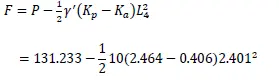
= 71.913 kN/m
The force to be resisted by the wale fixed around the sheet pile wall is 71.913 kN
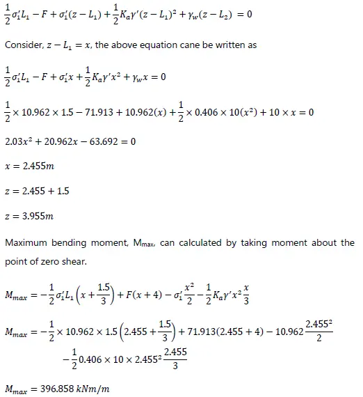
Calculate Maximum Bending Moment in the Sheet Pile
The maximum bending moment will be at zero shear. The point at which the shear force becomes zero can be calculated from the following equation assuming it is between L1 and L1+L2.
The following equation can be derived by considering the equilibrium.
Calculate the required section Modulus
Srequired = Mmax / σall
Based on the BS 4360: 1986, for grade 43A steel, yield strength can be taken as 275 N/mm2 when the thickness of steel less than 16mm and it is mild steel.
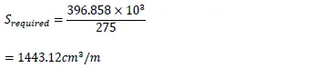
From the section property data, Sheet pile type FSP Type IIIA having section modulus 1520 cm3/m is recommended for the construction.
Further, sheet pile type having the required section modulus could be used.
Lateral loads calculated from the sheet pile design is used for the analysis and design of wale and struts that support the sheet pile wall.
This worked example does not cover the analysis and desing of the sheet pile wall supporting system.
The following figure indicates the summary of the desing of the sheet pile shoring design.
The article was written as Sheet Pile Retaining Wall and the Design of Excavation Support Systems could be referred for more information on the design of other types of shoring methods. Further, these articles include the worked example for ease of understanding.