There are a huge number of types of foundations using in building structures. Without any doubt, we need to have at least one type of foundation to construct a structure.
As discussed in the article how to determine the foundation type, we could select the most suitable foundation type.
Mainly, there are two types of foundations.
- Shallow Foundations
- Deep Foundations
So, let’s discuss each of the types of foundations in detail.
Shallow Foundations
As the name implies, shallow foundations are constructed at a show a depth.
The shallow foundation is also called as spread footings.
Though the foundation is placed in a shallow depth, depth of the excavation for foundations may need to extend for a considerable depth due to the weak ground conditions.
Soil improvements could be done as recommended in the soil investigation report for shallow foundations. Thus, depth of excavation some times increases.
Shallow foundations can be discussed under two main categories.
- Spread Footings other than the Mat (Raft) foundations
- Mat Foundations / Raft Foundations
Spread Footings other than Mat Foundations
There are many types of foundations that we can discuss under this subject.
Let’s discuss about each type in brief with the required information.
1. Pad Footings
It is also called as isolated footings.
The most widely used type of foundation in small to medium-rise buildings.
The simplest type of concrete foundation. It is very easy to construct and also less chance of occurring design and construction errors due to its simplicity.
Not like other types of foundations, it is very easy to design the pad footings. The following steps could be followed.
- Say axial Load is “N” (Serviceability limit stage), allowable bearing capacity of the soil is “BC”
- Aras of the foundation; A = N / BC
- Length/width of the foundation is √A
- Calculate ultimate load “UL” which is a factored load of dead load, live load, wind load, etc. Each load shall be multiply by the relevant factors.
- Calculate the ultimate pressure under the foundation = UL / A
- Since we know the pressure, the bending moment can be calculated. The bending moment at the face of the column is considered in the footing design.
- Assume the depth of footing and calculate the reinforcement.
- Check for vertical line shear and punching shear. That is checking shear stresses at the face of the column or at 1.5 x effective depth. This shear perimeter may very to standard to standard. The article punching shear design could be referred for more information.
- The depth of the footing is selected in such a way that it is not required to provide the shear links.
The worked example done for Eurocode Design of pad footing could be referred for more information.
2. Combined Footings
A combination of two columns by single footing can be identified as a combined footing. Further, when the columns are two close, increase of the area of footings due to the low bearing capacity, etc also reasons for combining the footings.
The design of combined footings is slightly different from the pad footings.
The article design combined footing states a worked example done for Eurocode 2.
3. Strap Footing Connected to Column
What is a strap footing? When we have to construct strap footings?
Strap footing is a kind of combined footing though the two footings are not connected. But they connected by a beam.
When the columns are at the boundary or very close to the boundary, columns cannot place in the center of the footing.
Place the column at the edge of the footing to create an unbalance moment and it leads to varying the pressure under the foundation.
The increase of the press close to the column could excessive settlement in the foundation. Therefore, to minimize the rotation of the footing, we construct a beam connecting two footings and columns.
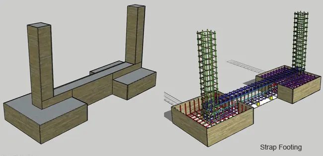
The design of footings is not that simple as isolate footing. It required more calculations and attention.
4.Strap Footing with Counter Weight
The beam is provided to transfer the rotation of the footing to the other column by means of shear force and bending moment. The upward reaction on the counter column balance the system.
Instead of a column, we can construct or place a mass concrete to balance the upward reaction.
The size of the block to be constructed is based on the maximum vertical upward reaction.

In addition, a strap beam can be supported by a restraining body such as concrete walls, base, etc. as indicated in the above figure.
5. Strip Footings
Strip footings are constructed when the gap between the columns is close or the applied load cannot be born by isolated or combined footings.
Constructing a strip footing increases the area and reduce the applied pressure on the soil.
These types of foundations are more suitable for low bearing capacity soils.
There are mainly two methods to design the strip footings.
- Design as a Rigid Foundation
In this method, the applied loads by columns are averaged over the length, and unform pressure is considered for the design.
- As a Flexible Foundation
Theories like a beam on elastic foundation are considered in the design. The variation of the soil pressure under the foundation is considered. Further, constructing the footing as a stirp reduces the different settlement.
The manual calculation is a bit difficult as we have to do more arithmetics.
Computer software could be used to do the analysis. Soil can be model as spring using the subgrade reaction method. In addition, we can use the line spring too. Then strip footing needs to consider as a line element.
The most suitable method is modeling the footing with area elements and soil with spring elements.
Soil spring or the subgrade reaction, Ks can be calculated from the following equation.
Ks = (FS) x 40 x BC
Where,
FS: Factor of safety applied to the soil to calculate allowable bearing capacity (we could consider the value in the range of 2-3)
BC: Allowable bearing capacity of the soil.
If we do the analysis by software like SAP2000, Etabs, Safe, etc., we can get the bending moments and shear forces that can be used to proceed with the design.
6. Inverted “T” Foundations
Further development of the strip footing is the Inverted T types of foundations. With the increase of the column axial loads, we have to provide higher footing thicknesses.
It is not an economical way of increasing the stiffness of the footing.
Therefore, beams are constructed together with the footing to have the additional stiffness.
Thus, the beam together with the footing provides the stiffness at the mid-span and beam along carry the bending and shear forces at the columns.
Footing thickness reduction with the introduction of the beam and footing designs for cantilever action from the beam.
A similar analysis procedure discussed under the strip footings could be adopted to analyze the inverted T footings.
Mat Foundations / Raft Foundations
Mat foundation which also identified as Raft Foundations is a combined footing that covers the whole area from the foundation.
These types of foundations are more suitable for low bearing capacity grounds.

Further, when the axial load increases the area of the foundation increases. We cannot provide isolated footing with the increase of the area of the foundation.
There are several types of mat foundations.
- Flat Plate
The flat plate raft foundation is a thick concrete slab. It has a uniform thickness in the whole area. Most prepared type of foundation as it is easy to construct when compared with other types.
Comparatively economical type of foundation due to its simplicity.
- Flat Plate and Foundation Thickened Under the Columns
Foundation subjected to bending and shear actions. Generally, the shear forces and bending moments are higher at the column foundation connection.
The article Punching Shear Design could be worth reading to know more about the selection of shear perimeter.
Therefore, it is required to increase the thickness of the foundation. Further, increasing the thickness of the whole foundation is not an economical option. Therefore, foundation thickness at the column increases in the downward direction.
Increasing the thickness in the downward direction is a bit difficult to construct. We cannot increase thickness in an upward direction if the floor (raft top level) is used for some other purposes like vehicle parking or any other.
- Flat Plate and Foundation Thickened Upward
The increase in thickness is as discussed above. When there are no limitation or the raft foundation top level is not using of any other purpose or the clear spacing of the pedestals are adequate for the purpose of using it, upward pedestals can be constructed.
- Beam and Slab Raft
With the increase of the axial load on the raft foundation, it could not be possible to proceed with a flat plate raft without increasing the thickness considerably.
Further, an increase in the thickness of the raft foundation is not an economical option. Having the beams connecting the columns increase the stiffness of the raft foundation and comparatively low thickness of the flat plate can be maintained.
The beam can be constructed in upward direction or downward directions based on the requirements.
Though the downward beams are more difficult to construct, we have to proceed with it if the floor is used for some purpose.
- Cellular Raft
Further increase in the column axial loads, required to increase the height of the beam in a beam and slab raft. In addition, increasing the beam height is not that economical option.
Therefore, a top slab is constructed creating a cellular raft. The cellular raft has a higher stiffness compared with other types of rafts.
- Pile Raft
In general, piles are connected to the superstructure through the pile caps.
With the increase, if the height of the buildings, the sizes of the pile caps are increasing. When we do not much gap between the pile caps, we connect all pile caps and construct pile rafts.
In addition, when the pile is not rested not rock or terminated in the soil, pile raft are constructed to get the support of the ground.
In these situations, both the pile and pile raft bear the applied loads from the superstructure. It is based on soil and foundation interaction.

As indicated in the above figure, with the settlement of the piled raft, mobilization of the loads occur. Initially, the pile starts taking the loads and gradually the raft pressure increasing. In the increase of the pile load, it mobilizes the full capacity and raft pressure increasing. Then the pile and raft reach the ultimate capacity which corresponds to the ultimate load.
The article published as the pile raft foundation could be referred for more knowledge.
Deep Foundations
Types of foundations constructed beyond the shallower depth are falling into this category.
Mostly, we try to construct structures on shallow foundation due to the cost of construction, difficulty in quality control and quality assurance, delaying project due to the time taken to complete the foundation, etc.
Mainly there are three types of deep foundations.
- Pile Foundations
- Diaphragm walls
Let’s discuss each activity one by one.
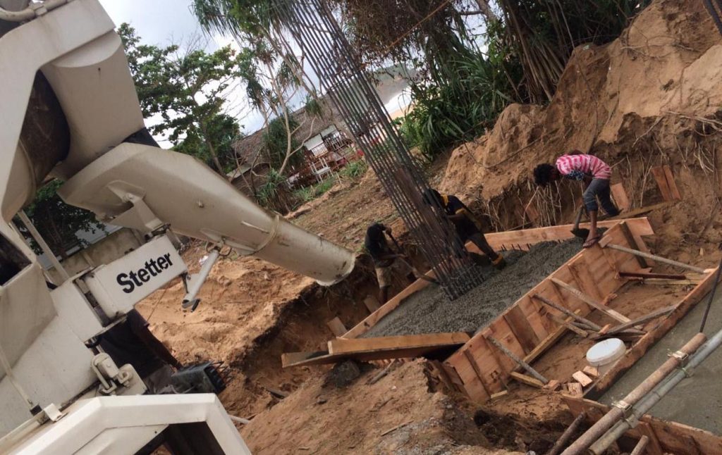
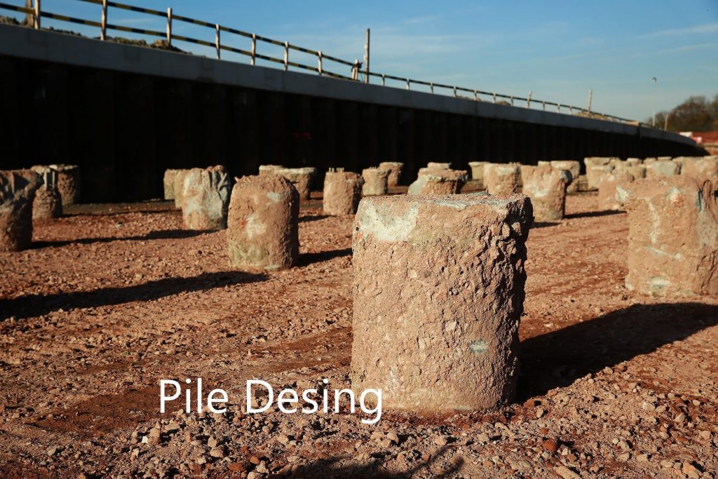
Pile Foundations
The most widely adopted method the build structures when compared with other types of foundations. Depending on the nature of the construction we could use different types of pile foundations.
Mainly following types of pile foundations can be identified.
- Cast in situ bored piles
- Driven pile (precast piles)
- Micro piles
- Sheet piles
- Timber piles
The article pile foundations discuss the design, construction, and testing aspects of pile foundations.
Diaphragm Walls
Diaphragm walls are a modern development of the foundation construction technology when compared with other types of deep foundations.
It is a concrete wall constructed vertically downward and socketed in the rock.
Though it is a wall, construction procedure is more similar to cast-in-situ bored piles.
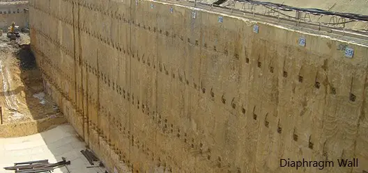
The construction of diaphragm walls has more advantages as follows.
- They can be used as structural elements to carry the loads.
- It could use to retain the earth in the basements.
- It can act as a watertight wall
- Vibrations and noise levels are less when compared with other construction methods.
Construction of the secant pile wall is more difficult and costly when compared with the diaphragm walls. Further, time is taken for the construction also comparatively lesser.