Pile foundations are constructed when it is not possible to build the structure on shallow foundations. Depending on the nature of the structure and due to the more reasons, selection of pile foundations is made as discussed in the article.
We concentrate on following the main topics in this article.
Pile Foundations – overview
Pile Foundations Design
Construction of PIies
Pile Testing
Let’s start with understanding…
What is a Pile Foundation?
It is a type of foundation that constructed deep into the ground and mostly circular sections are used in the construction.
The shallow foundations rest on the ground and they transfer the vertical loads directly to the soil. The capacity of the soil is represented as allowable bearing capacity and if the applied pressure is less than the allowable bearing pressure, the geotechnical design is ok.
However, in the pile foundations, different methods and different parameters are used.
Soil skin friction (positive and negative), skin friction of the weathered rock, skin friction in the rock, and end bearing of the rock are considered in the design.

Why When Piles Need to Support the Structure
- When the vertical loads applied on the foundation can not be carried by shallow foundations due to low bearing capacity.
- When there are week soil layers such as peat presents in the soil
- To carry the tensile forces applied to the foundation. Piles can be anchored into the rock to carry tensile forces.
- To carry lateral loads (compression) applied to the foundation. An inclined pile will be constructed to carry both the compression and tensile forces.
- When vertical loads are very high, especially in tall buildings, soil bearing capacity is not adequate to carry such loads. we need piles.
Factors affecting Design and Construction of Pile Foundations
- Loads from the superstructure
- Condition of the soil. Depending on the nature of the soil, the skin friction will be varying. When there are soil layers like peat, negative skin friction needs to be considered in the geotechnical design of the pile.
- Condition of the rock. RQD and CR values determined from borehole investigation are highly influential on the pile capacities.
- The cost of construction is also a major factor considered when selecting piles as a supporting system.
- Accessibility to the site shall be checked.
- Clearances from the boundaries shall be checked
- Limitation of the vibrations and sound levels shall be checked. Excessive vibration could cause damages to adjoin properties.
Types of Pile Foundations
This categorization was made based on the type of material used in the construction of pile and based on the nature of the construction.
- Bored Piles / Cast in situ piles
- Driven Piles/ precast piles
- Micro piles
- Sheet Piles
- Timber Piles
- Screw Piles
Bored Piles or Cast in Situ Piles
The most commonly and widely used type of pile. In majority of structures constructed from pile foundations, board pile can be observed.
Pile is socketed into the rock. Depending on the nature of the load and amount of the load, depth of embedment in the rock will vary.

Further, number of piles required to support a column depends on the capacity of the pile and the applied load.
Firstly, we find the geotechnical capacity and the structural capacity of the pile. Then the minimum of those values is taken as the capacity of the pile.
Since the applied load is known, the number of piles can be calculated.
Bored piles are constructed as single piles or group piles based on the applied loads. Generally, group piles are required to support shear cores, shear walls, lift cores, etc.
Driven Piles / Precast Piles
These are pre-fabricated piles.
They are constructed when the applied load is comparatively low when compared with bored piles.
Further, precast piles are not driven up to the rock but they terminated or inserted into a hard soil layer. There should be a dense soil layer to rest the pile and to provide the end bearing.
These piles are mainly friction dominant piles though there is an end bearing.

Driven can be done manually by falling a mass into the pile or by using a vibrating piling machine.
Piles are available in different sizes starting from 400mm. Further, depending on the nature of construction, even smaller sizes can be made.
Further, these types of pile foundations are widely used in low rise buildings when they can not be constructed with shallow foundations.
Micropiles
Micro piles are quite popular in low rise building construction.
When the ground condition is weak and there is no adequate bearing capacity to carry the loads from the superstructure, a deep foundation needs to be constructed.
In this background, if look at the available options; we have to select the type of foundation from bored piles, precast piles, and micro piles.
Out of those, bored piles are more costly in general when compared with the other two types.
Depending on the nature and the type of loads from the superstructure, the selection of the piling type is made.
Further, when these types of foundations are constructed, it is advisable to get the recommendation from a geotechnical engineer.
The design shall be done based on those parameters provided in the soil investigation report and those shall be verified after the construction by doing necessary tests.
A micropile is a steel casing filled with concrete. When required and as the diameter of the micropile is increasing, the reinforcement cage also can be placed inside the pile to improve its structural capacity.

Micro piles are used in the abutment construction and bridge pier constructions. Lateral loads applied on the abutment can be transferred to the ground by inclined micro piles.
In pier construction, three piles or six piles cost in hexagonal shape used to carry the vertical loads.
The main risk of this type of construction is the corrosion of steel. If exposed or allowed to meet with the requirements for corrosion, the pile could fail.
However, on the other hand, there is less risk as a pile is underground and there is less chance of getting all ingredients for corrosion.
If the structure is to be built in a coastal area, much attention on the protection of the steel casing shall be made.
Micro piles are constructed from steel casings 150, 200, 300mm, etc.
Sheet Piles
Sheet piles are also can be considered as a type of pile foundations though they mostly do not use to support the structures directly like other types of piles.
For example, sheet piles use to support the soil around the structure and it acts as a permanent structure too. Removal or considering as permanent work depends on the nature of the construction and condition of the ground.

Further, sheet piles are widely used in construction to retain the earth for excavations. In deep basement constructions, also as indicated above, properly anchored sheet piles can be used.
In addition, it is useful in the construction of cofferdams also.
There are different types of sheet piles based on the profile and connection arrangement. Apart from that, we can select the suitable sheet pile based on the required section modulus as per the design requirements.
The article, sheet pile retaining wall discuss the stability design of sheet pile retaining wall.
Timber Piles
Not only the present construction, but ancient construction is also have used better technology.
They knew that when there is a weak soil, piling needs to be done. So they have used sustainable material to do it.
Even now when construction or expansion is done, timber piling can be observed.
Especially the buildings and bridges have been constructed on timber piles.
Timber piles are durable, economical, and sustainable.
Special timber that has good durability properties to be used.
Please carry the load from the skin friction and end bearing.
Constructions in very weak areas where heavy machines cannot be approached, timber piles are used.
Screw Piles
The pile is like a screw as indicated in the following figure.
The nature of the screw depends on the type of construction.
Further, there are different types of screw piles.

In building connections or any other constructions such as bridge construction, screw piles can be used.
Pile Foundations Design
Once the piles are selected as the foundation type according to the recommendation of the geotechnical investigation report, evaluation of the number of piles is done.
Then, we need the pile capacity.
There are two-component in the pile foundations to evaluate the plie capacity.
We take the lesser of below.
- Geotechnical Design
- Structural Design
Geotechnical Design of Piles
Evaluation of the geotechnical capacity of the pile is done based on the soil condition and the rock condition of it is anchored in the rock.
The geotechnical capacity of the pile can be represented from the following equation
Qu = Qp + Qs
Where
Qu – Ultimate geotechnical capacity of the pile
Qp – Ultimate end bearing of the pile
Qs – Ultimate skin friction of pile
The allowable capacity (Qall) can be calculated as
Qall = Qu / FoS
FoS – Factor of Safety; varies 2.5 -4
Further, there are different methods to calculate the allowable capacity of the pile. The method of application of factor of safety may differ from country to country based on their local standards.
Some time a separate factor of safety is applied for both the end bearing and skin friction and the singe factor of safety is also used.
It is observed that a low factor of safety like 2.0 is also used for skin friction. When design it is highly recommended to local standards.
Mainly there are five components connected with the geotechnical capacity of a pile.
- Skin friction of the soil (positive skin friction and negative skin friction)
- Skin friction of the weathered rock
- Skin friction of the rock
- End bearing of rock
- End bearing of soil
If the pile is terminated at soil (hard layer) in the case of precast piles, end bearing in the soil is used. If the pile socketed in the rock (cast in situ bored piles) end bearing in the rock is used to calculate the pile capacity.
The above five parameters are provided by the geotechnical recommendation based on the borehole investigation data.
If we know the soil parameters, we can calculate the skin friction values as per the equations.
The following methods are available to calculate the skin friction of soil.
Skin Friction in Sand
- Based on overburden and friction angle between soil and pile
- Correlation with standard penetration test (SPT)
- Correlation with cone penetration test (CPT)
Skin Friction in Clay
- λ method
- α method
- β method
- Correlation with CPT
The end bearing of the soil also can be calculated from different methods proposed. The following methods are widely used by designers.
Soil End Bearing
- Meyerhof’s method (sand/clay)
- Vasic’s method (sand/clay)
- Coyle and Castello’s method (sand)
- Correlation with SPT and CPT
Skin Friction of Rock
The skin of the rock is determined based on the condition and type of rock.
Generally, the ultimate skin friction of the fresh rock and weather rock is provided in the geotechnical investigation report.
We have to apply the factor of safety to calculate the allowable capacity. If allowable capacity is given we can use it directly.
Point Bearing of Rock (End bearing)
The evaluation is based on the test results. Most of the time, the uniaxial compressive strength (UCS) test is carried out to find the strength of the rock.
The relationship between the UCS and end bearing is used to determine the final figure.
The RQD and CR values shall also be checked when determining the pile capacities and socketing lengths as they represent the condition of rock.
In summary, we will receive the necessary geotechnical parameters such as skin friction and end bearing values form the geotechnical investigation report. What we need to do is apply the necessary factor of safety and calculate the geotechnical capacity.
Structural Design of Pile
The allowable concrete stress in the bored cast in situ piles are considered as 0.25fcu in most of the standards. There are only slight deviations.
- ACI 318 : 0.25 fcu
- EC2 : 0.26 fcu
- CP4 : 0.25 fcu
However, pile needs to check for buckling especially when it is constructed on a weak groud. Thus, buckling analysis for pile foundations is carried out.
And considering the same, structural design or the reinforcement design can be done.
There are two methods/steps to design a pile.
- Calculate the Critical Buckling Load and check whether it is greater than the applied load.
- Carryout more rigorous buckling analyses and carrying out the design.
The summary of calculation steps is as follows. Further reading shall be done before carrying out design.
Step 01
Calculate the critical buckling load (Pcr).

Step 02
Based on the Pcr, soil springs, rotation at the top of the pile(may have some rotational fixity), etc, find the effective length (Lcr).
Step 03
Since we know the applied loads, effective length, and pile diameter, we can design the pile using a conventional method or using a software.
Key factors to be considered in the pile foundations design are summarised as follows.
- Evaluate the geotechnical capacity and structural capacity of the pile and take the less as pile capacity.
- Divide pile capacity by the applied load (column load or applied load; serviceability limit state) to find the number of piles.
- When there is a group of piles to design, the individual load shall be calculated based on the load center and the geometric center of each pile. Loads shall be distributed based on the position of the pile.
- If there is more than one pile, minimum gap between the pile shall be 2.5 x pile diameter.
- The increase of the gap between the pile will not allow you to use truss analogy to pile cap design. Therefore, gap between piles is maintained 2.5 – 3 times pile diameter.
- Attention to the negative skin frictions shall be made when organic soils are present. Otherwise, estimation of pile capacity will be wrong.
- Pile bucking shall be checked when there are very weak soils such as peat for a longer depth.
- Attention on RQD and CR values shall be made when decided the socketing lengths.
- Generally, as per most standards, allowable tolerance for construction deviations is 75mm. This shall be considered in the pile cap design. Special attention shall be made when there is a single pile. The moment due to the centricity shall be carryout by the ground beams. Therefore, it shall be considered in the ground beam design.
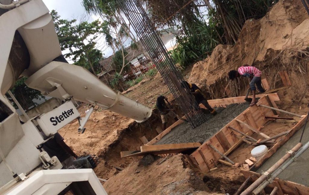
Construction of Pile Foundations
Let’s discuss the basic steps to be followed in the pile construction. The following procedure is discussed in relation to the cast in situ piles.
The following tolerances are allowed by different standards as allowable deviations during the construction.
| Code | Allowable Tolerance |
| ACI-336 | 4% of diameter or 75mm; whichever less |
| BS EN 1536 | 100mm; for pile diameter(D) ≤ 1000mm
0.1D for 1000<D≤1500 150mm D>1500 Design for rake less than 1 in 15 limits to 20mm/m Design with a rake of between 1 in 4 and 1 in 15 limits to 40mm/m |
| CP4 | 75mm |
| BS 8004 | Not more than 1 in 75 from the vertical or 75mm
Deviation of up to 1 in 25 permitted for bored piles drilled at rakes of up to 1 in 4 |
Pile Construction Steps and Key Aspects to be Attended
- Carrying out the setting out
- Start removing the topsoil up to the rock level. It shall always try to maintain the position of the pile as specified in the drawings though there is an acceptable tolerance of 75mm generally.
- Start rock coring and monitor the depth of stating the rock coring. In this case, it shall make sure that the coring is done in the fresh rock and not in weathered rock.
- It shall be measured with the samples, rate of penetration, borehole log data, site other pile depths if any.
- Due to the difficulties in locating the fresh rock, the first plie will be cast closer to a borehole. Then the other parameters can be evaluated. Based on that we can proceed with the piling.
- Visual observation are made check the quality of the rock.
- In addition, testing methods such as point load test could be used to check the strength of the rock. Point load test results can be correlated to find the end bearing of the pile. If it is not satisfying, rock coring shall be done until the sound rock is found. The article construction material testing techniques could be referred for more information on testing.
- Once the coring in the rock is completed as per the socketing lengths, cleaning will be done.
- The main purpose of cleaning is to remove mud, sand, etc. in the bentonite to remove. This is also called flushing.
- There are parameters to checked for to make sure pile is clean adequately. The following figure indicates the limiting values. Those values will be changing from specification to specification.

- Once the bentonite in the excavation reaches the specified limits, flushing is stoped.
- Then the tremie pipe is placed in the excavation.
- Then slowly concrete is poured into the tremie. Once it is filled, the tremie is lifted by a very little amount allowing the concrete to flow out.
- This concrete will gradually move up with all the mud and impurities at the bottom of the pile. Then again tremie is filled with concrete and allow concrete to flow out.
- It shall make sure the end of the tremie pipe is always within the fresh concrete. It enables always fresh concrete to mix with fresh concrete and top concrete layer moving up gradually.
- Further, it is very important to control the rate of pouring concrete to avoid lifting the reinforcement cage. If the rate is higher, cage will be lifted.
- Repeat this until the concreting is completed.
Testing of Pile Foundations
Not like other foundations, we cannot see what happens underground.
Nothing visible…
How to decide whether we have constructed the pile correctly with..
- Adequate cover to the reinforcement
- Without necking
- Without bulging
- Without concrete mixings with bentonite
- Without cavities(like honeycombs) in concrete
- Without mud at the bottom of the pile
- Etc…
Therefore, we need to do testing of the pile to make sure it is constructed properly.
It is the responsibility of the contractor to carry out testing of piles in consultation with project consultant and third-party testing agency.
Pile Testing Methods
Mainly there are four types of pile testing methods.
- Pile Integrity Test (Low strain integrity Test)
- Dynamic Load Test ( High strain dynamic test)
- Static Load Test
- Cross Hole Sonic Test
Pile Integrity Test
The easiest method to predict the integrity of the piles.
Bulgings, neckings, socketing, etc can be predicted with this test.
This best method to identify the defective file but can not assess the pile capacities.
It provides an initial warning of whether the pile is defective.
The pile integrity test is used to identify the piles to be testing by other methods such as pile dynamic test and pile static load test.
In addition, this testing method is not costing much when compared with other tests. Further, all the piles are tested with this method.
Dynamic Load Test
The most widely used method to find the pile load capacities in present construction.
Not like a static load test, it provides results instantly. Plie capacity can be obtained at the site just after the testing. However, further analysis will be done to provide accurate answers after analysis with Softwares like CAPWAP.
We can obtain the pile skin friction and end bearing developed to the test load.
Initially, the pile testing will be simulated with software and the falling height of the hammer is decided in such a manner that it will not generate tensile stresses than that can be allowed or that can carry by the pile reinforcements.
This is called wave equation analysis (WEAP). With this method, it is not required to apply the hammer load several times until we find the testing load.
WEAP provides the relationship between test load, compressive stress, and tensile stress development.
Therefore, testing can be done very easily.
Static Load Test
This more reliable and conventional method used in pile testing. Since all the measurements are taken manually, we have an idea of what happens with the increase of the load.
We increase the load on the pile up the testing load specified in the pile design and it reduces gradually.
Pile deformation is monitored and checked whether it is within the limit.
Cross Hole Sonic Test
This test is to used to check the condition of the pile. It can be used to check the condition of the concerning work within the holes placed in the pile.
Conduits are placed in the pile. Then the testing instrument is placed in the pile and check. Transmitter and receiver is used to check the condition of the pile.

Based on the wave speeds it predicts the condition of the pile. Further reading on the testing method could be referred from Wikipedia article crosshole sonic logging.