Construction material testing is done from the beginning to the end of the projects. Before starting the construction some of the materials are tested and others are testing during the construction. Depending on the applicability of the materials, tests are carried out to check the suitability of the material for construction and also testing is done to check whether the used material has achieved its strength.
The following list provides the 27 construction material testing.
- Sieve Analysis
- Hydrometer Analysis
- Moisture Content Determination
- Atterberg Limit (LL, PL, SL)
- Specific Gravity
- Bulk Density /Unit weight
- Swell Index Test
- Proctor Compaction(Std, Mod)
- CBR Test
- Permeability Test (Constant Head/Falling Head)
- Lugeon Test
- Organic content of soil
- Unconsolidated Undrained Triaxial Compression Test
- Unconfined Compression Test
- Field CBR Test
- Consolidation Test
- Aggregate Crushing Value (ACV)
- 10% Fines Value of Aggregates
- Aggregate Impact Value (AIV)
- Los Angeles Abrasion Value (LAAV)
- Specific Gravity of Aggregates
- Water Absorption of Aggregates
- Flakiness Index
- Elongation Index
- Field Density Test
- Unconfined Compression Test of Rock
- Point Load Strength Index of Rocks
- Non Destructive Hammer Test on Concrete
- Compressive Strength Tests on Concrete Cubes/Paving Blocks/Hollow Blocks
- Compressive Strength Test of Clay Bricks
Overview of Construction Material Testing
Sieve Analysis as Construction Material Testing
Particle size analysis is done in three stages

Sieve analysis is a method of classification of construction materials such as sand, quarry dust, etc. The particle size distribution is obtained through this test as a requirement of construction. For example, when filter materials are selected in dam construction, the particle size distribution of selected material shall be with the specified range.
Soil Classification is categorizing the soil according to their engineering behavior. Knowing the gradation of the soil is very important to the design engineers to judge the behavior of the material. Further, testing shall be done to verify the engineering properties of the material.

In a sieve analysis test, the percentage of different grain sizes distribution is obtained. Sieve analysis test is used to find the particle size distribution of course aggregates and fine aggregate, and the hydrometer analysis, which discussed next, is used to categorize finer particles.
Equipements: Balance, Set of sieves, Cleaning brush and Sieve shaker
Hydrometer Analysis
Hydrometer analysis is used to determine the particle size distribution of finer particles of soil. The physical process of sedimentation is used for hydrometer analysis. The grain size distribution is very important for the designs and knowing the exact distribution could be used for optimized design.
Further, for fine-grained soils, sieve analysis may not give the correct results as fine-grain soil consists of fines in the range of 0.075mm to 0.0002mm. It is not practical to use such small sieves and there is a high chance of losing the material during sieving.
Equipment: Mixer(blender), hydrometer, sedimentation cylinder, control cylinder, Thermometer, beaker, timing device
Atterberg Limits as Construction Material Testing
Atterberg limits are the measure of the water content of fine-grained soil and it is a widely used construction material testing method for clay soils. There are three limits that consider in defining it.
- Shrinkage Limit (SL)
- Plastic Limit (PL)
- Liquid Limit (LL)
Depending on the water content soil behave in for stages namely solid, semi-solid, plastic and liquid. Each stage of soil behaves differently and their engineering properties are also different. Thus, the boundary of each four stages is defined as SL, PL, and LL as shown in the following figure.

Shrinkage Limit
Limit at which the solid stage of the clay is changing from solid to semi-solid is know as the shrinkage limit. Further, it is defined as the water content where the further loss of moisture will not result in any more reduction in volume.
The shrinkage limit is tested as per ASTM D4943.
Plastic Limit
The plastic limit is tested by rolling out a thread of the find portion of soil on a flat, non-porous surface as defined in ASTM D4318.
The plastic limit is defined as the moisture content where the thread breaks apart at a diameter of 3.2mm. A soil is considered non-plastic if a thread cannot be rolled out down to 3.2mm at any moisture possible.
Liquid Limit
Liquid limit is defined as the water content at which the behavior of the clayey soil changes from a plastic state to the liquid stage.
The liquid limit can be determined using the Casagrande cup method or a Cone Penetrometer.
Specific Gravity
The specific gravity of soil is defined as the unit weight of the soil mass divided by the unit weight of distilled water at 4°C.
Specific gravity is determined by Pycnometer.
Apparatus: Volumetric Flask Pycnometer, Vaccum Pump, Mortar and Pestle, Balance weighing 0.01g and Thermometer.
Bulk Density of Soil
Bulk density is also known as dry density, is an indicator of soil compaction.
It is calculated by the dry density of soil is divided by the volume of soil.
Bulk density can be tested as per the guidelines given in the website Soil Quality Website.
Standard Proctor Compaction Test as Construction Material Testing
Proctor compaction test is a test method of experimentally determining the optimal moisture content at which a soil will become most dense and achieve its maximum dry density. The originate test is most commonly referred to as the standard proctor compaction test and later it was updated to a modified proctor compaction test.
According to Proctor, the compaction of the soil is depends on the following factors.
- Type of soil
- Moisture content
- Compactive effort
- Dry density of soil
The following standards could be referred to the testing procedures.
- AASHOT: T99-86
- ASTM: d698-91
- BS1377: Part 4
The guidelines are given on the website “civilseek” could be referred for more information.
CBR Test as Construction Material Testing Method
California Bearing Ratio (CBR) is used to evaluate the strength of subgrade for deciding the thickness of the subgrade and its properties in road and pavement construction.
This is a penetration test and it is one of the commonly used test methods to evaluate the strength of the subgrade. These test values are used to evaluate the thickness of the pavement from the empirical curves developed and it is the most widely used method to design the flexible pavements.
CBR can be defined as follows.
CBR = (P / Ps) 100%
where,
P – Measured pressure at the site where we need the CBR
Ps – Pressure to achieve equal penetration on standard soil
There are two types of CBR values; Soaked and unsoaked CBR values. The harder the surface, the higher the CBR value.
Permeability Test as Construction Material Testing
The ability to seep the water through the soil is measured in the permeability test. Knowing the permeability of the soil is very important in hydraulic designs as it could even erode a dam. Further, there are limitations to be considered in the design based on the design specifications.
There are two methods for evaluating the permeability of the soil
- Constant Head Test
- Falling Head Test
Permeability of soil is specified in terms of the coefficient of permeability (k). There are many reasons for knowing the permeability of soils.
- Permeability influence the settlement of saturated soil under loads
- Design of earth dams are much relying on the permeability of the soil used
- Design of the clay core of the rockfill dams is also depended highly on the permeability of clay used
- Stability of slope and retaining structures depend on the permeability of the soil
- Filters made from the soil are based on the permeability
- Filters for rockfill dames are also designed the permeability properties
- Knowing the permeability of the soil is important to plan the drainages in high dams.
Hydraulic conductivity is also known as permeability. Soil permeability depends on the following factors
- The viscosity of the liquid
- Distribution of Pour sizes
- Distribution of Grain sizes
- Void ration
- Degree of saturation of soil
Constant Head Test – Permeability Test
- Done for coarse-grained soils
- Testing is done for the laminar floor; k is independence of hydraulic gradient
- Testing is done as per ASTM D2434
Falling Head Test – Permeability Test
- Done for both coarse-grained soils and fine-grained soils
- The similar procedure followed in testing constant head permeability is used
Lugeon Test
Lugeon test is an in-situ test that is used to estimate the average hydraulic conductivity of the rock mass.
Lugeon test is used to measure the amount of water injected into a segment of the bored hole under a steady pressure; the value is defined as the loss of water in liters per minute and per meter borehole at an over-pressure of 1MPa.
The lugeon coefficient is used commonly used to state the condition of the rock. The lugeon coefficient which by definition is water absorption measured in liters per meter of test-stage per minute at a pressure of 10kg/cm2.
The following equation could be used to evaluate the lugeon value.
Lugeon Value = (q /L ) x (P0 / P)
Where,
q – flow rate (liters/minutes)
L – Length of the borehole test interval (m)
P0 – Reference pressure of 1 MPa
P – Test pressure (MPa)
Typical lugeon Values of rock can be given as follows. However, these values shall be verified during construction as required by the design.
| Lugeon Value | Conductivity classification | Rock discontinuity condition |
| <1 | Very low | Very tight |
| 1-5 | Low | Tight |
| 5-15 | Moderate | Few partly open |
| 15-50 | Medium | Some open |
| 50-100 | High | Many open |
| >100 | Very high | Open closely spaced or voids |
In construction, especially in dam construction, it is required to control the seepages as it could lead to severe issues as discussed under the permeability test.
Therefore, knowing the permeability of the rock is very important to the designers and the construction team to minimize the seepages of water.
Further, there are cracks in the rock and water seepages are inevitable if it kept as it is. Therefore, it shall be controlled. Based on the design parameters and as per the specification of the project, a lugeon value shall be maintained during the construction.
Grouting is done to seal the cracks in the rock. Holes are drilled up to the depths specified by the design based on the borehole investigations done for design.
After doing the grouting, a borehole is drilled and sample are taken at the depths at which it is required to check the lugeon values. Samples are tested for lugeon value and compart with the design value for satisfaction. If not satisfied, further grouting shall be done. The procedure is repeated until it is satisfied.
Organic Content of Soil
Organic matter is the most complex, dynamic and reactive component in the soil. The content of the organic matter in the soil affects the physical properties of the soil and its chemical reactivity.
More adversely, it affects the compressibility of soil and shear strength of the soil. The shear strength of the soil is a very important factor when the shallow foundation is constructed. Low shear strengths could lead to the failures of the foundation systems.
Further, the organic content of soil affects the ability to retain the water, biological activities and water, and air infiltration rates.
The organic content of the soil is tested as per the ASTM D 2974.
The content of the organic matter is specified as a percentage from the ratio mass of organic content to the mass of dry soil.
The test is done by heating the soil sample to a temperature of about 4400C to burn the organic matter. When the initial weight (Wd) of the dry soil is known and the weight of the burned soil is known (Wb), the organic content can be calculated as follows.
Organic Content = [(Wd – Wb) / Wd] x 100%
Triaxial Compression Test as Construction Material Testing Method
There are three triaxial tests.
- Unconsolidated Undrained Triaxial Compression Test
- Consolidated Drain Triaxial Compression Test
- Consolidated Undrained Triaxial Compression Test
Advantages of Triaxial Test
- Pour pressure and volumetric change can be measured directly
- Stress distribution in the failure plane is uniform
- Testing is suitable accurate studies
- Specimen free to fail in weaker plane
Disadvantages of Triaxial Test
- The apparatus is costly
Unconsolidated Undrained Triaxial Compression Test
Triaxial test is done to evaluate the mechanical properties of soils such as soil, rock and other granular materials. It measures the compressive strength of the soil in terms of total stress.
ASTM states “in this test method, the compressive strength of a soil is determined in terms of the total stress, therefore, the resulting strength depends on the pressure developed in the pore fluid during loading. In this test method, fluid flow is not permitted from or into the soil specimen as the load is applied, therefore the resulting pore pressure, and hence strength, differs from that developed in the case where drainage can occur”
The test is done by a saturated specimen is subjecting to confined fluid pressure in a triaxial cell.

Three samples are tested generally and they are subjected to different confining stresses.
The test is done as per the ASTM D2850-15.
Attention to followings shall be made when using the tested strengths.
- The undrained unconsolidated strength can be used in cases where the loads are applied rapidly without allowing sufficient time to dissipate the pour water pressure and consolidation to occur during the loading period.
- Undrained unconsolidated strength could not be applied in cases where the loading conditions significantly differ from the testing conditions.
Field CBR Test
CBR test is done to assess the strength of the subgrade materials. This test is done at the site as an in-situ test. This very common construction material testing method as it is comparatively easy to proceed.
The penetration curved is plotted and the CBR values are calculated as per the laboratory.
Consolidation Test
Consolidation is a process of gradual change in the volume of soil in response to the change in pressure.
Generally, soils consist of soil grains and pour water. When the load is applied on the soil, initially the pour water absorbs the pressure without changing the volume, creating excess pour water pressure. Due to the high pressure, water moves away to release the pressure while gradually transferring the pressure to the soil. Soil takes up the pressure change and shrinks in volume. This process is called consolidation.
Consolidation is a time dependence process that could last very long like even 100 years.
Therefore, knowing the settlement criteria due to the consolidation is very important in the foundation and structural design. The rate of consolidation and total consolidation will be worth knowing during the design.
Mostly the clay is subjected to the consolidation settlement.
There are two types of consolidometers to test the consolidation
- Floating Ring
- Fixed Ring

Testing of consolidation can be done as per ASTM D2435
There are two types of consolidation considered in geotechnical design.
- Primary Consolidation
- Secondary Consolidation
Primary Consolidation
Primary consolidation settlement is more significant than the secondary consolidation settlement in inorganic clays and silty soils. However, in organic soils, secondary consolidation settlement is more significant.
This method assumes the consolidation occurs one dimension.
Secondary Consolidation
At the end of the primary consolidation(at the end of the dissipation of excess pour water pressure) some adjustment is observed that is due to the plastic adjustment of the soil fabrics. This stage of consolidation is called secondary consolidation.
Creep, viscous behaviour of the clay-water system, compression of organic matter, and other processes result in to cause the secondary consolidation settlement.
Though the secondary compression of the sand is negligible, peat is a soil having very high organic content causes a significant impact with the settlement.
Aggregate Crushing Value (ACV)
The aggregate crushing value is a relative measure of the resistance of an aggregate to crushing under a gradually applied compressive load.
It is defined as percentage by weight of the crushed material obtained when the test aggregates are subjected to a specified load under stabilized conditions.
The strength of the aggregate used for road construction is expressed by a numerical index.
Aggregates with lower crushing values give a longer service life.
In road construction aggregates with lower crushing strength are used for longer life span and for more economical performance. Use of weak aggregate with higher crushing value, they would crush under traffic loads in road producing smaller pieces creating debonding of the binder.
Testing can be done as per BS 812: Part 3.
There is no explicit relation between the aggregate crushing value and its compressive strength. However, the crushing value is greater for a lower compressive strength. According to the BS 812: Part 3, the maximum limit for aggregates used in structural concrete shall be 30 and it shall be 40 for lean concrete.
When the crushing value is 25 to 30, the test is insensitive because the weaker material is crushed before the 400 kN load is reached and compacted in a manner that further crushing is reduced. For such materials, a ten percent fines value test is suggested by BS:812, Part 3.
10% Fines Value of Aggregates
10% fines aggregate crushing values is the load required to crush a prepared aggregate sample to give 10% material passing 2.36mm (ASTM No. 8) sieve after crushing.
The ten percent fines value is a measure of the resistance of aggregate crushing subjected to loading and it is applicable to both weak and strong aggregates. Fine aggregate is defined as those passing 2.36mm sieve.
10% = weight of the fines aggregates / weight of all aggregates
In this test, unlike the standard crushing value test, a high numerical result denotes a higher strength of the aggregate.
BS 882: 1983 prescribes a minimum value of 150 kN for aggregates to be used in heavy-duty concrete floors finishes, 100 kN for aggregates to be used in concrete pavement wearing surfaces, and 50 kN when used in other concretes.
Aggregate Impact Value (AIV)
Due to the vehicle movement on the road the aggregates are subjected to impact resulting in their breaking down into smaller pieces. The aggregates should, therefore; have sufficient toughness to resist their disintegration due to impact. This characteristic is measured by the impact value test.
The aggregate impact value provides a relative measure of the resistance of an aggregate to sudden shock or impact, which may differ from its resistance to gradually applied compressive load.
It is the percentage of fines produced from the aggregate sample after subjecting it to a standard amount of impact.
The below count is 10 regarded as strong, and above 35 would normally be regarded as too weak for use in road surfaces. Aggregate Impact Values and Aggregate Crushing Values are often numerically very similar and indicate similar aggregate strength properties.
The aggregate impact test is considered to be an important test to access the suitability of aggregates as regards the toughness for use in pavement construction.
Testing can be done as per BS 812
Some typical values used to categorize the aggregate are as follows.
| Aggregate Impact value | Classification |
| <10 % | Exceptionally strong |
| 10-20% | Strong |
| 10-30% | Satisfactory for road surfacing |
| >35% | Weak for road surfacing |
Los Angeles Abrasion Value (LAAV)
Los Angeles Abrasion Value test is the measure of aggregate toughness and abrasion resistance such as crushing, degradation and disintegration.
The Los Angeles abrasion value method is commonly used to determine the abrasion characteristics and to classify the granular materials used in road and pavement construction. The abrasion resistance of materials can significantly affect the service life of road pavements when exposed to long-term dynamic traffic loads.
When vehicles travel on the road it contacts with the aggregate in the surface and as a result abrasion effect can be observed. Therefore, the aggregates used in road construction should have sufficient resistance to abrasion.
Testing could be done as per ASTM C 131: Resistance to Degradation of Small-Size Coarse Aggregate by Abrasion and Impact in Los Angeles Machine.

The Los Angeles abrasion test is to produce abrasive action by the use of standard steel balls, which when mixed with aggregates and rotated in a drum for some specified time for a specific number of revolutions also causes an impact on aggregates. The percentage wear due to relative rubbing action between aggregate and steel balls determined and known as Los Angeles Abrasion Value.
Los Angeles Abrasion Value = (Original weight – Weight retained on #12) / Original Weight
There are several drawbacks in this test method.
- The time needed to perform the test
- The operational noise and
- The dust generated during the test
- The space required for the machine
Specific Gravity
The specific gravity of the aggregate is the measure of the density of the aggregate with comparted to the density of the water at 230C.
Specific gravity is used in calculations and it is considered to be a measure of the quality of the aggregate. Aggregates with low specific gravity can be considered as weaker than those with higher specific gravity.
Specific gravity is tested according to ASTM C127.
Water Absorption of Aggregates
Course aggregate continue 40% -80% of concrete volume. Therefore, it is very important to study the behavior of the coarse aggregate.
The absorption of water by aggregates provides an idea about the internal structure of the aggregates.
More the absorption of the water the more the porosity of the aggregate and those type of aggregates are not suitable for construction unless it is found to be acceptable in terms of hardness and impact tests.
Aggregates having the water absorption in the range of 0.1% – 2% are normally used for road surfaces.
Testing could be done as per the ASTM C127.
Flakiness Index
Flaky particles are defined as the particles having least dimension is 0.6 times lesser than the mean particle size.
The maximum allowable limit of the flaky particles in the mix is 30%. If it exceeds this value then the mix is considered unsuitable for construction
Flaky and elongated particles could create an adverse effect on the concrete and bituminous mixtures. Flaky and elongated particles tend to lower the workability of concrete mix which may lead to long-term durability issues. For the bituminous mix, flaky particles are liable to break up and disintegrate during the pavement rolling process.
Flakiness index is defined as the percentage by weight of flaky particles in a sample, and it is calculated by expressing the weight of flaky particles as a percentage of the total weight of the sample.
It can be tested as per BS812.

Knowing the Flakiness index and the elongation index, which discuss next, is very important during the design and at the construction stage. It the responsibility of the construction team to check them and make sure they are within the limit.
- Degree of the compaction depends on the particles size and shape
- Flaky and elongated particles are considered unsuitable for base coarse construction as they may cause weakness with possible loading.
- Flakiness index shall be limited to 30% irrespective of aggregate size as per BS 1241
- Both the tests Flakiness and elongation are not considered particle size below 6.3mm
Elongation Index
The elongation index is defined as the content of elongated particles in the sample as a percentage of total weight.
Elongated particles whose one dimension is grader than 1.8 times the other dimensions.
Generally, the increase of the flaky and elongated particles in a concrete mix could lead to a low workable mix due to the increase in the surface area.
Elongated particles can be tested as per BS 812.

Elongated particle are limited to 45% in construction as increase beyond could create an undesirable mix.
Field Density Test
The density of the soil needs to be tested at the site as one of measure to check whether the expected completion of the soil is achieved.
Field density of soil can be testing using the following methods
- Sand Replacement Method or Sand Cone Method
- Core Cutter method
- Water Replacement Method of Field Density Test
- Rubber Balloon Method
- Heavy oil Method
- Nuclear Moisture Density Meter
The sand replacement method is more commonly used in construction. Dry density test carried ou to check the compaction of the soil layers.
Testing can be done as per ASTM D446-82 or BS 1377 part 4.
Form the test the compaction can be calculated and it can check whether it is within the limit for the tested layer.
Unconfined Compression Test of Rock
The Unconfined Compression Test is used to find the Unconfirmed Compressive Strength (UCS) of a rock. This is widely used construction material testing method used to determine the bearing capacity of a rock based on the correlations of them.
Unconfirmed Compressive Strength (UCS) stands for the maximum axial compressive stress that a specimen can bear under zero confining stress.
Since the stress is applied to the specimen along its longitudinal axis, the unconfined compression test is also called the Uniaxial compression test.
Unconfined compressive strength is widely used in geotechnical designs as it provides a clear indication on the strength of the rock.

In pile design and construction, UCS value is considered to determine/specify the end bearing capacity of the rock. There are charts that can be used to find the end bearing capacity of the rock. In addition to the UCS value, there are other parameters such as fractures/discontinuities, faults and weathering in the rock considered in specifying the end bearing for pile foundations.
The unconfined compression test is a laboratory test and it can be tested as per ASTM D 7012.
Point Load Strength Index of Rocks
The Point load test is an index test used as a measure of determining the strength of the rock. This is a popular construction material testing method in pile construction.
The test can be used to estimate other characteristics of intact rocks with which it correlates, such as uniaxial compressive and tensile strength.
This is a simple test and does not require much-sophisticated equipment. Further, less cost and time compared with the Unconfined uniaxial compression test has added advantages of the point load test.
The test can be done in a laboratory or in the filed.

In pile construction, this test is very useful to get an idea about the strength of the rock by correlating it with uniaxial compressive strength. Termination of the pile or deciding the socketing length could be done with the test results.
Non-Destructive Hammer Test on Concrete
Rebound Hammer test is known as the nondestructive hammer test. Name itself imply the idea about the test.
In this test, no damage or sample taking is not done. The hardness of the concrete is tested based on the reflection of the hammer for the applied force to the concrete.
The article written on the web site on Non-Destructive Testing could be referred for further information on the Rebound Hammer test and other tests.
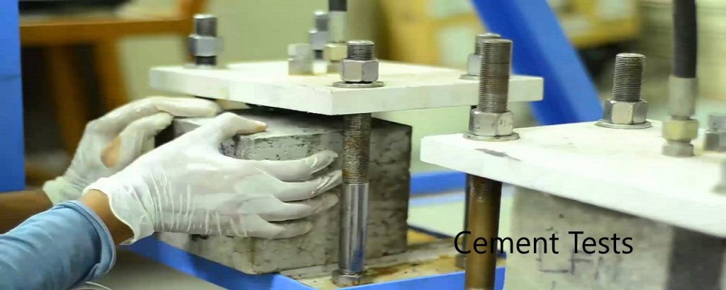
Compressive Strength Test on Concrete Cubes/Paving Blocks/Hollow Blocks
Compressive strength of the concrete, paving blocks, hollow blocks, etc are considered in the design as one of the major factors. It the base of the design finalization.
For example, the compressive strength of the concrete exists in almost all the equations considered for the design. Bending, axial, tensile, shear, etc. strength depends on the characteristic strength of the concrete,
Therefore, it is very important to verify it at the construction stage as a quality assurance measure.
Compressive strength is determined based on the type of the material and testing dates are as specified in the design.

Concrete is tested in 7days and 28 days or it could be done in 28 days and 56 days if the concrete strenth gain is slow. Properly cast cubs a placed in a bath are tested. Approval of the particular concrete pour is done based on the conformity criteria specified in the relevant standard or as given in the specification.
Compressive Strength Test of Clay Bricks
Testing can be done is the same machined used to test the concrete cube strength.
Generally, characteristic strenth of burned clay brick is in the range of 5N/mm2 – 10N/mm2
Brick is the most widely used construction material for walls. Further, brick is used as the load-bearing elements in the construction.
Testing can be done as per the guidelines given in the ASTM C67/C67M. Further, the same guideline is used for testing saturated clay tiles. Sampling procedures and testing methods are stipulated in the standard. In addition, there are more testing can be done with the same guideline. Standard test methods for sampling and testing brick and structural clay tile could be referred for more information.