Punching shear is a failure mechanism when structural elements subjected to concentrated load. Failure occurs in perimeter defined away from the concentrated load. Slabs, pile caps, footings, raft foundations, etc. element is subjected to punching action and they need to be designed for it.
The punching shear perimeter is considered as the critical section that a shear failure could occur. The following figure indicates the typical punching shear perimeter. The selection of the critical perimeter could be varied depending on the relevant standard.
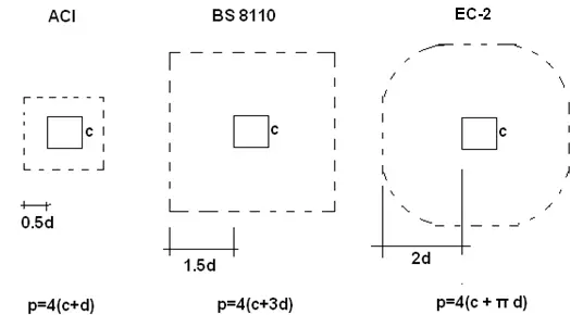
As indicated in the above figure, different standards use different values to define the punching shear perimeter. The selection of the perimeter could be varied with the other factors also.
Punching Shear Stress = V/bd
Where’
V – applied force
b – length of the perimeter
d – effective depth.
Punching shear stress shall be less than allowable shear stress; V<Vc
Punching shear checks are carried out for the following elements generally to avoid punching shear failures.
- Normal Slab
- Flat Slab
- Pile Caps
- Footings
- Raft foundations
Punching shear perimeter could be varied by standard to standard as discussed above.
Let’s discuss the variation of punching shear perimeter as per different codes
Punching Shear Perimeter as per Eurocode 2
Consideration of different perimeters is the main difference between most of the methods other than the various equations used on shear capacity calculations.
Distance to be considered for critical perimeter from the concentrated loading is also depending on the arrangement of the concentrated load. Further, the location that the concentrated load applied also needs to be considered when defining the critical shear perimeter.
The following figure indicates the method of defining the punching shear perimeter for a slab.
The shear perimeter is considered as 2d from the face of the column.
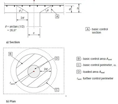
The nature of the support or the concentrated load needs to be considered when defining the shear perimeter. The following figure indicates the method of finding the shear perimeter.
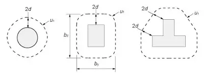
In addition, it is required to consider the location of the column to define the shear perimeter. Length of the shear perimeter is one of the factors that affect the shear stress.
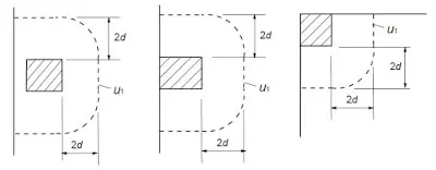
Generally, we have to maintain the 2d distance. However, it has to be based on the other boundary conditions. Total length shall be calculated as indicated above when we designing as per Eurocode 2.
Punching Shear Perimeter as per BS 5400 Part 4
BS 5400 Part 4 also provides a clear indication of calculating the punching share perimeter depending on the different arrangement of boundary conditions and support/loading area.
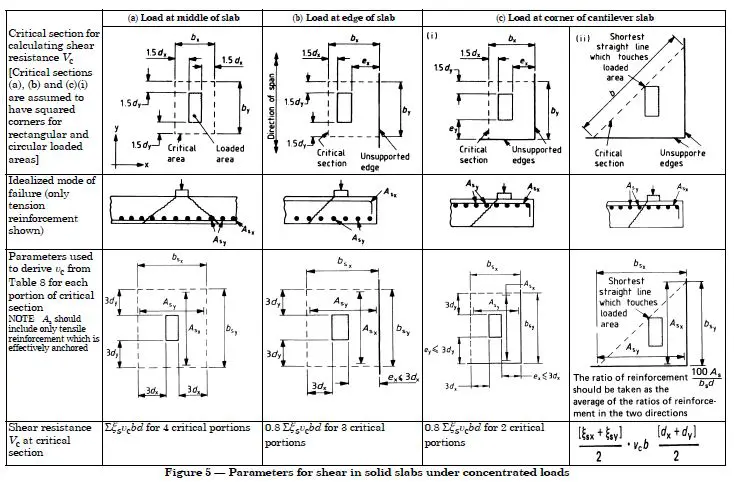
The information provided in BS 5400 is very useful. And it covers almost all the different cases that could arise when we design slabs, pile caps, flat slabs, footings, raft foundations.
Distance to the critical shear perimeter is considered as 1.5d in BS 5400 Part 4. BS 8110 is also considered the same shear perimeter.
Further, these definitions could be used when designing with other standards also. The distance to the shear perimeter could be taken from the relevant standard.
Punching Shear Perimeter as per ACI
ACI defines much less punching shear perimeter when compared with other codes. It is 0.5d. The following figure indicates the shear perimeter to be considered as per ACI standard.

Though the perimeter is less, we cannot conclude that it is always a conservative design without considering the other factors. However, apparently, it seems that ACI has much concern about the punching shear design.
Punching Shear Design Example
Consider the design of footing for punching shear as per the BS 8110.
According to the BS 8110 Part 1, shear perimeter shall be at 1.5d.
Consider following data
- Effective depth 350mm
- Applied force in the area 1100kN
- Size of the column 300mm
- Characteristic strength of the concrete 25N/mm2
- Assume(for this example) allowable shear stress Vc = 0.6 N/mm2
Check punching shear at the face of the column
Shear stress = 1100×1000 / (4x300x350) = 2.62N/mm2
Allowable stress = 0.8(fcu)0.5 = 0.8(25)0.5 = 4N/mm2 < 5N/mm2
Hence Ok.
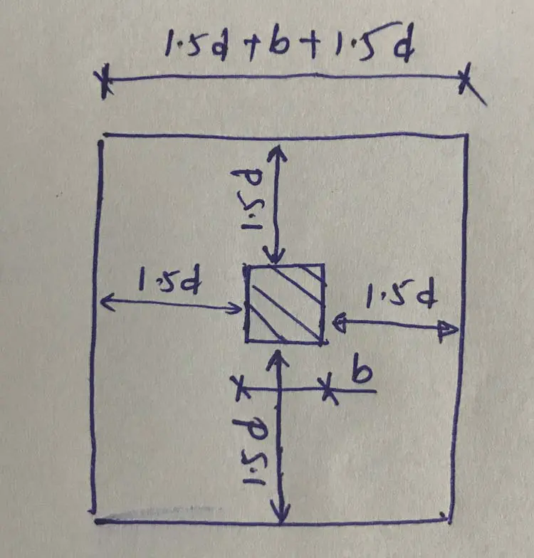
Consider Shear perimeter at 1.5d
Length of share perimeter = 4x(1.5d+300+1.5d) = 4x(1.5×350 + 300 + 1.5×350) = 5400mm
Shear stress, v = 1100×1000 / (5400×350) = 0.582 N/mm2
V<Vc, therefore, punching shear is ok.
Similarly, punching shear reinforcement design can be done for other elements also.
It is not always possible to meet the requirement; V<Vc. When the shear stress increases than the shear capacity, it is required to provide the reinforcements.
Usually, we avoid the shear reinforcement and the thicknesses and reinforcements are adjusted to avid links. However, in some of the elements such as raft foundations, it is not advisable to increase the section and area of reinforcement considerably.
This results in increasing the cost of construction. If we provide shear links, it could be a comparatively less cost. When we increase the thickness, it may be required to increase in the whole area. However, there are methods to increase the depth of the section in a critical section.
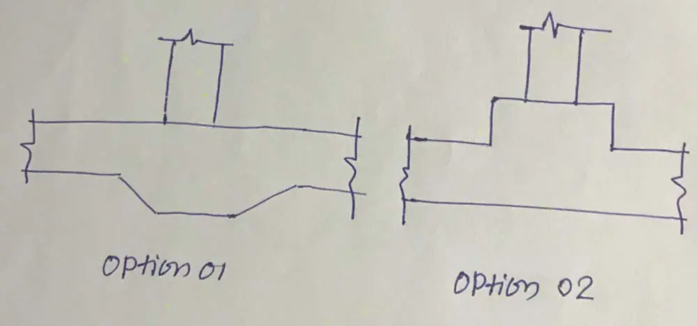
Both the option is applicable, especially for raft foundations. Option 01 is difficult to construct when compared with option 02. Continuation of waterproofing, reinforcement tieing, etc. have to be done with extra effect if we use the option 01.
Option 02 is much easier than option 01. The projection could be constructed in the second stage. However, when the raft slab will be used as a basement floor or ground floor, the projection will create an obstruction. Therefore, option 01 is preferred in such situations.
Reinforcement Detailing for Punching Shear
Lets discussed it with an example where we have to provide shear links to carry the shear stress.
Design of raft foundation for punching shear
Data considered for example
- Design carry out as per BS 8110 Part 1
- Column axial load 3000 kN
- Column size 450×450 mm
- Punching shear force 1.5d from the face of the column 500kN/m
- Effective depth of the raft 550mm
- Provided tension reinforcement T25@150 (3272mm2/m)
Punching Shear at Face of the Column
Shear stress = 3000×1000 / (4x450x550) = 3.03N/mm2
Allowable stress = 0.8(fcu)0.5 = 0.8(25)0.5 = 4N/mm2 < 5N/mm2
Hence Ok.
Consider Shear perimeter at 1.5d
Shear stress = 500×103/(1000×550) =0.91 N/mm2
As per the provided reinforcement area and effective depths
Shear capacity, Vc = 0.532 N/mm2
Spreadsheet could be referred to simply calculate the reinforcements and shear links.
As per BS 8110 Part 1 Table 3.16,
Vc + 0.4 = 0.532 + 0.4 0.932 N/mm2
Vc < V < Vc+0.4
Therefore, provide a minimum area of reinforcement.
Note: depending on the applied shear force, relevant formula shall be selected from Table 3.16.
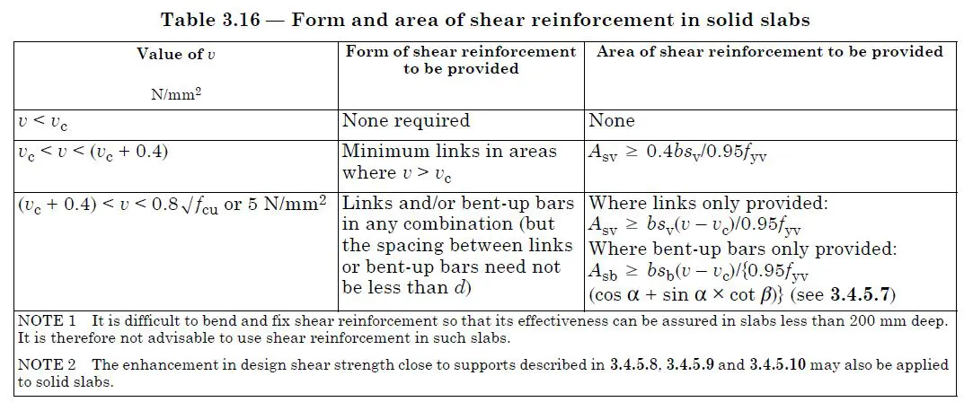
Asv ≥ 0.4bsv/0.95fyv
We provide the shear links in both the direction not like other elements. In beams, there are only two legs mostly. Similarly, we have to consider the number of legs per meter length to calculate the spacing of the links in the other direction.
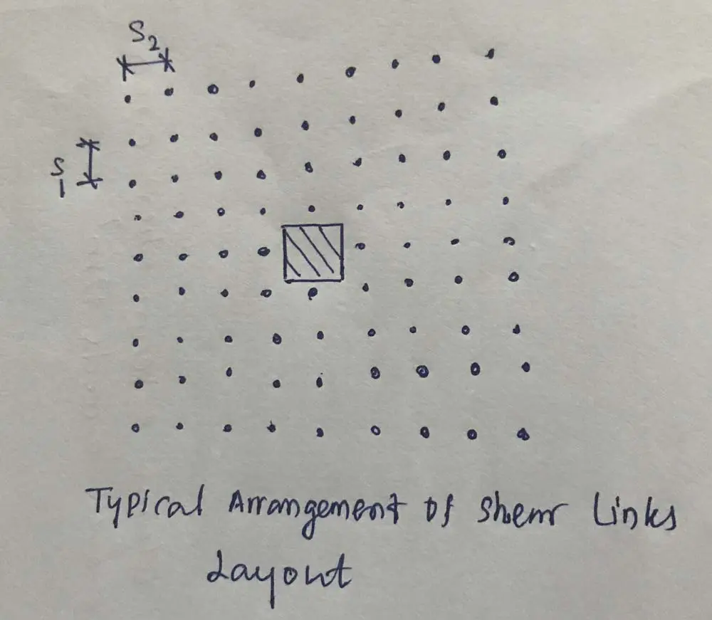
We usually consider the spacing of the main reinforcement when selecting the spacing of the shear links. Since the main reinforcement is at a spacing of 150mm, consider links spacing as 300mm.
Then,
Asv = 377mm2/m
377≥ 0.4x1000x sv /( 0.95×500)
Sv ≤ 478 mm
Therefore, consider T12@300 in the other direction also.
Shear links shall be provided in the area up to V<Vc.
The following type of links is provided in the reinforcement design.
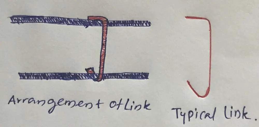
The above-discussed method can be used to design for punching shear in slabs, footings, and raft foundations. However, there is a slightly different approach is used in the shear design of pile caps.
An enhancement factor is also considered in the design. A similar method is used in flat slab designs.
The article pile cap design could be referred for more information about these kinds of designs.