Shear links are provided to carry the shear forces induced by the applied loads on structural elements. The most wildly discussed element connected with shear links is the concrete beams. There are no beams without links though other elements could skip providing links as the design requirements.
A load applied to a structural element is transfer to its supports in the form of stresses. In designs, we considered them in different forms. They are the bending moment and shear forces. Shear force is the force that transfers the applied load to the support.
As discussed above, shear link reinforcement is inevitable in the beam. At least we must provide minimum shear reinforcement in beams as per the structural design standards.
Lest discuss why we need shear links
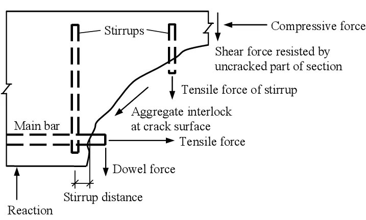
As we can see in the above figure, the failure plane in the shear is angular. However, we provide share links in the vertical direction as it is the easiest way to hold them in practice.
There are other ways of providing shear reinforcements. The bent up bars are more effectively contributed to the shear resistance and they are placed in a perpendicular direction to the shear failure plane.
However, it is very difficult to place the bent up bars within the beams as shear rebar due to the reinforcement congestion. Further, they are provided in the area where the shear is critical.
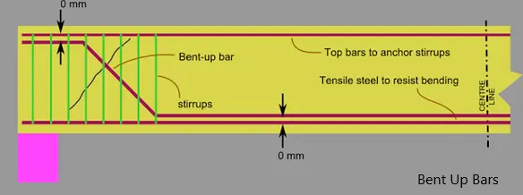
As we can see in the above figure, bent up bars can be placed in the beams, the main reinforcement bar can continue as bent up bar in the beam.
Let’s discuss specifically the type of shear reinforcements in beams.
Beam Shear Links
When beam shear reinforcement is provided, we need to follow the standard method of detailing of reinforcements. Most of the standards such as BS 8110, ACI 318, Eurocode 2, etc, follow almost similar arrangements of shear reinforcements.
The article beam shear design to Eurocode 2 could be referred for more information about design procedure.
Further, reinforcement agreements made for seismic requirements are more similar.
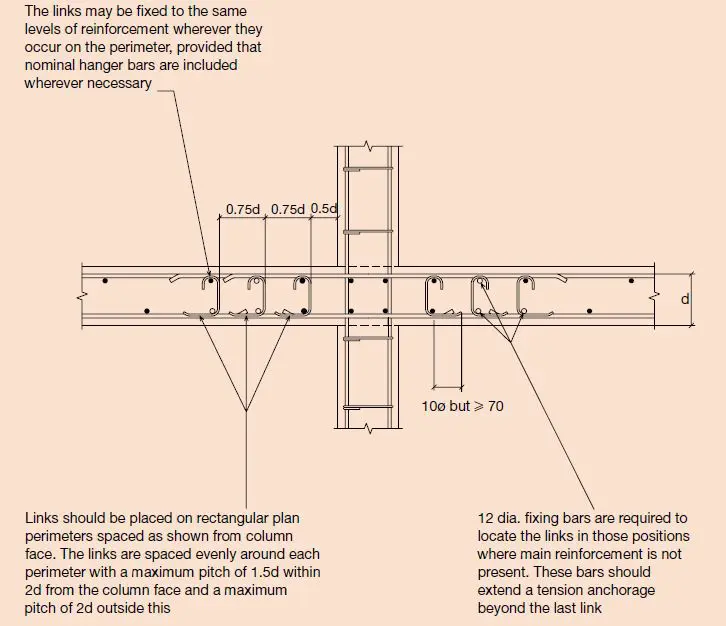
The following figure, extracted from the Standard Method of Detailing indicates the type of links and their arrangement in beams.
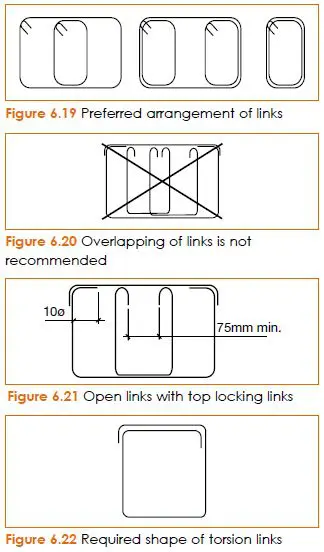
Depending on the detailing requirements and as per the reinforcement requirement by the design, shear links are provided. In addition, constructability issues are also considered in the reinforcement detailing.
The following figure also extracted from the same standard. The figure indicates some of the key aspects considered in detail as per the Eurocode 2.
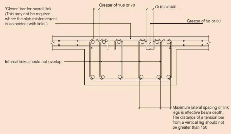
These guidelines shall strictly be followed when detailing of shear reinforcements. Further, detailing shall not be limited to the above methods and relevant standards shall be referred.
In summary, the following can be highlighted
- No shear links shall be overlapped as indicated
- Attention shall be made on the shape of the link when there are torsional moments
- Compression bars shall be restrained as per the relevant guideline requirement by links
- Compression bars shall also be restrained by shear links as stipulated in the referred standards.
Slab Shear Links
Providing shear links in slabs are not common. However, we usually provide shear links in flat shabs. Flat slabs are critical in shear depending on the magnitude of the loads applied.
Not like beams, there are special types of share link arrangement and shear links use to carry the shear forces.
Further, bent up bars also can be used to resist the shear forces.
The following figure taken for the Standard Method of Detailing indicates some of the important things to be considered in detail.
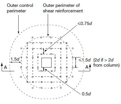
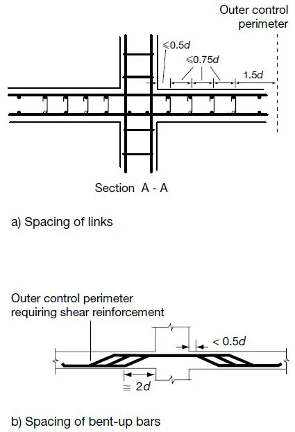
The above values are based on the detailing requirement of the Eurocode 2. However, as applicable, this arrangement and technical information could be used.
Additionally, the following detail could also be referred for further details on the arrangement of shear links.
Column Shear Links
Mainly there are two purposes of providing shear links in columns
- To avoid buckling
- To carry the shear forces
There is a minimum requirement of links to be provided in a column to avoid it buckling when the loads are applied.
The widely known fact is the buckling failure of columns. If links are provided and reinforcement designs were done considering the correct effective heights, buckling failures can be avoided.
On the other hand, we provide links to columns to carry the shear forces. As discussed in the article about structural forms, the frame structures where there are no shear walls, carries the shear forces.
In this type of structure, columns are carrying the shear forces induced by lateral loads.
It is a mus to have good lateral load resisting systems in buildings. However, in frame structures, the frame carries the lateral loads to the foundation.
There are different detailing requirements for columns. Normal structures we provide shear links as per the relevant standards. However, when we design/detailing for seismic effects, seismic detailings shall be referred.
The following key points can be highlighted related to this area.
- When the spacing of a bar exceeds 150mm from the restraining bar (the bar having a shear link), a shear link shall be provided to restrain that bar.
- The spacing of the links shall be as per the relevant standards
- Mostly the links spacing are maintained as 150mm for seismic requirements near in beam-column joints. The article on Seismic Detailing could read for better understanding.
Raft Shear Links
Providing shear links in a raft or mad foundations are not that common as they can be avoided by different methods.
We can increase the depth where the shear forces higher or we can increase the are of tension reinforcement to increase the shear capacity.
However, an increase in depth is not always possible as there are limitations to it. According to BS 8110, beyond a certain depth, 400mm, increase of the depth is not contributed to increasing the shear capacity directly.
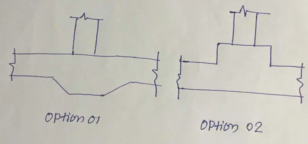
As indicated in the above figure, these options can be followed to avoid the shear links. However, it not always preferred option due to the construction difficulties in option 01 and the obstruction made by the kerb in option 02.
Anyway, let assume, we provide shear links.
So we have to provide shear links in the area where the design shear is greater than the allowable shear.
Similar concepts or the layout as discussed in the flat slabs are used in the raft foundations also.
However, the arrangement of the shear links is somewhat different.
The following figure indicates a typical share link detail.
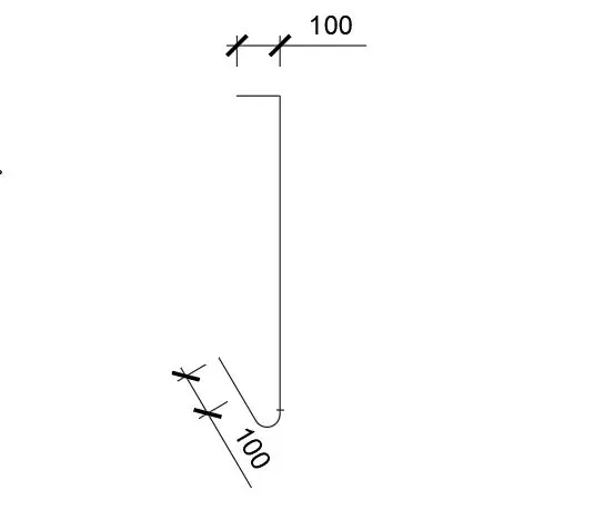
Links are provided around the loaded area and the number of links to be as per the design requirements.
Shear links in Walls
There are mainly to types of walls that may need shear links.
- Retaining Walls
- Shear Walls
Retaining walls
Retaining walls are subjected to out of plane actions. Shear forces and bending moments are generated due to the out of plane loadings.
Therefore, the shear links shall also be in the direction of the shear to avoid shear failures. A similar type of shear link indicated above for raft can use for retaining walls.
Links can place horizontally in between the vertical bars.
The number of links to be provided in the vertical direction and horizontal direction shall be as per the design requirements.
Method of calculation of the number of shear links can be referred from the article about punching shear design.
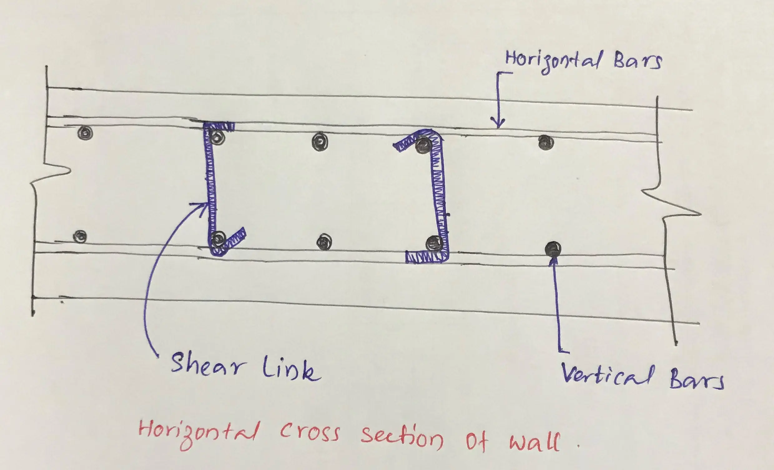
Shear Walls
Shear walls are designed to carry the lateral loads applied to them. Further, in place action of the shear wall is used to resist the forces.
Therefore, the share links are provided in the direction of the shear. Close links are provided mostly. However, open links as indicated in the following figure is also used.
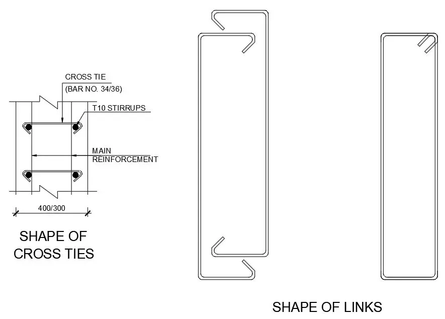
The number of close links depends on the shear forces applied on the shear wall. The article all about shear walls could be referred more to shear walls.