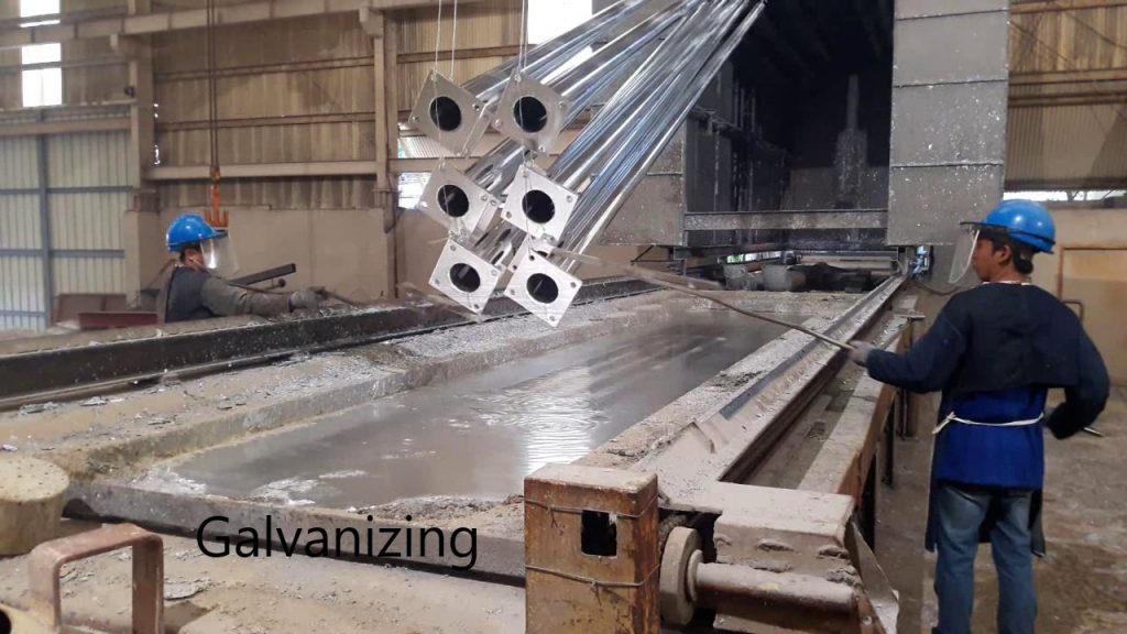
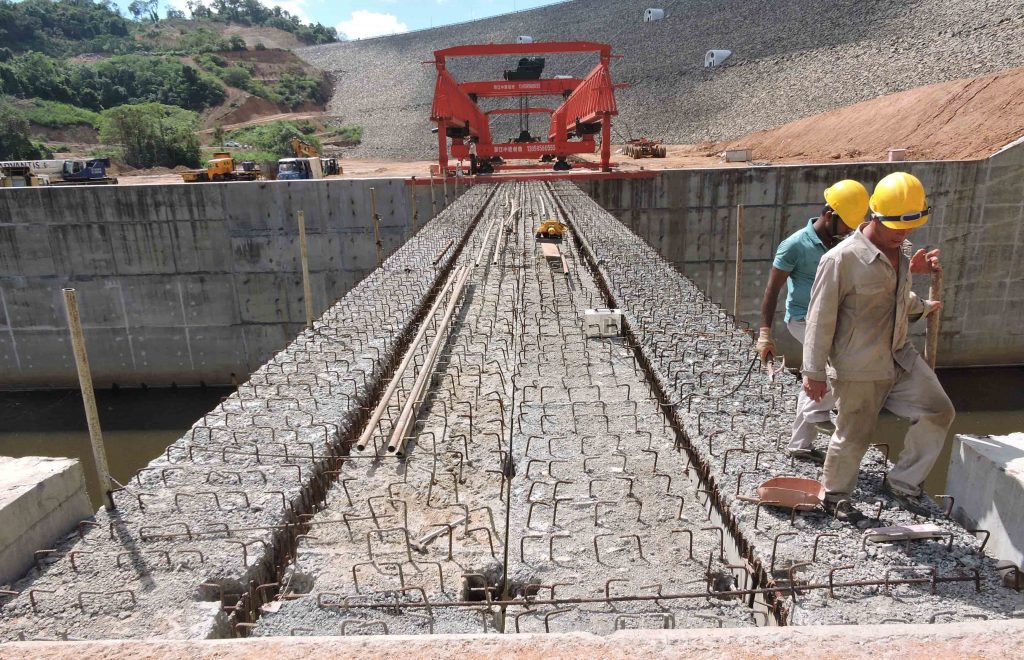
The thrust block design is done to carry the forces generated due to the changes in the direction of the liquid flowing pipes. Change of the momentum creates forces on externally on the pipes. Thrust blocks are constructed to carry these forces whether these forces can not be born by the pipe itself.
This article discusses the literature on the thrust block design and thrust block design example.
CRIA Report 128 Provides comprehensive guidelines to be followed in designing the thrust blocks.
The method of calculations is subjected to the following assumptions as mention in the CRIA Report 128.
- Flow cross-sectional areas are constant (except for tapers)
- Viscous Loss in components is negligible, except for partially closed valves.
- The dynamic pressure head is small (flow velocities rarely exceed 3 ms-1, equating to a dynamic head < 0.05 bar).
- One-dimensional flow theory is valid
- The liquid in the pipe is a Newtonian fluid, e.g. water.
- Thrust forces from any friction generated as a result of a pressure drop associated with a change in flow velocity are considered negligible for applications within the scope of this report.
There are two methods given in the guideline to calculate the thrust.

The following table and related charts could also be used to calculate the forces on the thrust block.

One of the above methods can be used to calculate the forces on the thurst block.
Thrust Block Design Example
The following assumptions and design data were considered in the analysis and design.
- Density of concrete 24 kN/m3
- Grade of the concrete of grade 25
- Minimum characteristic strength of steel 460 N/mm2
- Cover to the reinforcement below the ground level 75mm
- Working pressure 6bar (= 600kN/m2)
- Slope of the pipe 450
- Internal angle of friction 300
- Allowable bearing pressure 150 kN/m2
- Density of soil 18 kN/m3
Calculation of the loads on the thrust block, calculation of the weight of the thrust block, check of bearing and reinforcement design is done in this section.
CALCULATION OF REACTION OF 1200mm DIAMETER PIPE
Pipe angle from horizontal = 450
Horizontal force = PA(1-cosθ) = 600 x π x 1.22 (1-cos45)/4 = 200 kN
The horizontal force is in the direction of the pipe.
Vertical reaction = PA sinθ = 600 x π x 1.22 x (sin45)/4 = 480 kN

Consider the arrangement of the thrust block as shown in the above figure. The width of the thrust block is considered as 2250mm and length consider as 2000mm.
Weight of the concrete = [2.25 x 1.05 x 2 – π x 1.22 x 2 / (2 x 4) ] x 24 = 87 kN
Check for Bearing
Vertical reaction = 480 kN
Since the working pressure is considered for the calculation of the thrust forces, the vertical reaction above can be considered to check the bearing.
SLS vertical force = 480 kN
Vertical reaction on soil = 480 + 87 = 567 kN
Area of the thrust block = 2.25 x 2 = 4.5 m2
Pressure under the base = 567 / 4.5 = 126 kN/ m2
The pressure is less than allowable bearing pressure (150 kN/m2). Therefore ok.
Checking for Lateral Stability
Due to the change of the angle, there are vertical and horizontal forces. The horizontal forces are generated in the direction of the pipe. In this calculation, it is considered that the pipe will not be taking any force.

As shown in the above figure, consider pipe is laid on 2m below the ground level.
From the above calculation,
Horizontal force on pipe (SLS) = 200 kN
Design force = 1.5 x 200 = 300 kN
Ground resistance = Force due to lateral force difference + base resistance
Ground resistance = (σp-σa)Af +τbAb
Calculate the active earth pressure coefficient = (1-sinθ)/(1+sinθ)
Ka = (1-sin30)/(1+sin30)
Ka = 0.333
Calculate the passive earth pressure coefficient = (1+sinθ)/(1-sinθ)
Kp = (1+sinθ)/(1-sinθ)
Kp = 1.5
Since the forces are applied on the concrete block and pipe, consider pressure in the middle of the pipe.
Active pressure = Kaγh = 0.333 x 18 x 2 = 12 kN/m2
Passive pressure = Kpγh =3 x 18 x 2 = 108 kN/m2
Side surface area = pipe +thrust block = 0.6 + 1.05 = 1.65 m
Side area = 1.65 x 2 = 3.3 m2
Resistance force = (108 – 12) x 3.3 = 316.8 kN
Applied horizontal force = 300 kN
Therefore, the thrust block is horizontally stable. Further, in this calculation, the base resistance was not taken into account. Consideration of the base resistance will increase the resistance force further.
Further above calculation can be verified as follows.
Applied force SLS = 200 kN
Resistance = 316.8 kN
The factor of safety against sliding = 316.8/200 = 1.58 >1.5
Hence Ok.