Design of Deep Beam as per CIRIA Guideline
Looking for design of deep beam? Different guidelines have been developed for the design of deep beam by researches. CIRIA guideline, Eurocode 2, ACI code, Canadian Code, etc. are more commonly used.
The procedure mention in the CIRIA Guide 2 is discussed in the section. Further, this discussion is based on the book Reinforced Concrete Deep Beams edited by Prof. F. K. Kong.
Following limitations shall be taken into account when beams are designed with CIRIA Guideline
Single Span Beam : (Effective span / depth ratio (l/h) less than 2.0.
Continuous Beam : (Effective span/ depth ratio (l/h) less than 2.5.
Further, CIRIA Guide could be used with BS 8110;1985.
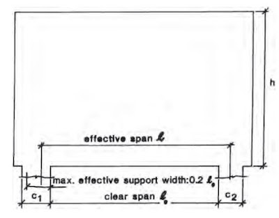
Effective span (l) shall be obtained from the following the equation
l = l0+[lesser of (C1/2 and 0.1l0] + [lesser of (C2/2) and 0.1l0]
Active height (ha) can be obtained from the following the equation
ha = h or l whichever is the lesser
DESIGN OF DEEP BEAM FOR BENDING
STEP 01
Bending capacity of the section
Mu = 0.12fcubha2 ; where fcu – concrete cube strength, b – width of the beam
STEP 02
If l/ha ≤ 1.5 go to step 03. If l/ha > 1.5 check whether the applied moment is less than Mu
STEP 03
As > M / 0.87fyZ
Where
M = Applied bending moment
fy = Characteristic strength of the reinforcements
Z = 0.2l + 0.4ha for single span beams
Z = 0.2l + 0.3ha for continuous beams
STEP 04
The reinforcement area calculated under STEP 03 needs to be distributed over a depth of 0.2 ha .
Anchor the reinforcement bars to develop at least 80% of the maximum ultimate force beyond the face of the support.
The main reinforcement must be anchored so that the concrete within the area of support realized upon for bearing is adequately confined.
DESIGN FOR SHEAR
Based on the loading position calculation of the shear stresses are done.
Bottom Loaded Beams
STEP 01
Vu = 0.75bhavu
vu is the maximum shear stress taken from the BS 8110 Part 1 Clause 3.4.5.2 and Part 2 Clause 5.4
STEP 02
Check whether the applied shear force does not exceed the Vu
STEP 03
Provide hanger bars in both the side the support the load. The design stress of the reinforcements shall be considered as 0.87fy. Hanger bars shall be anchored by a full bond length above the active height ha or, alternatively, anchored as links around the longitudinal bars at the top. Click here for further reading on the design of hanger reinforcements in beams.

STEP 04
Nominal horizontal web reinforcement shall be provided over the lower half of the active height ha and over a length of the span equal to 0.4ha measured from each support. The area of this web reinforcement should not be less than 80% that of the uniformly distributed hanger steel, per unit length. The bar spacing and reinforcement percentage should also meet the crack control requirements.
Top Loaded Beams

STEP 01
Calculate the effective shear span(xe) which is to be taken least of :
- The clear shear span for a load which contributes more than 50% of the total shear force at the support
- l/4 for a load uniformly distributed over the whole span
- The weighted average of the clear shear spans where more than one load acts and none contributors more than 50% of the shear force at the support. The weighted average will be calculated as Σ(Vrxr)/ΣVr where ΣVr = V is the total shear force at the face of the support, Vr an individual shear force and xr = clear shear span of Vr
STEP 02
Calculate the shear capacity (Vu) from the following equations.
Vu = 2bha2 vc / xe for ha /b < 4
Vu = 1.2bha2 vc / xe for ha /b ≥ 4
Vu = bhavu
where vu is the value taken from BS 8110 : Part 1 Clause 3.4.5.4 and Part 2 : clause 5.4.
STEP 03
Check the applied shear force does not exceed the shear capacity calculated in Step 02.
STEP 04
Provide nominal web reinforcement in the form of a rectangular mesh in each face. The area of nominal reinforcements shall not be less than that specified in BS 8110 Part 1 Clause 3.12.5.3 and Clause 3.12.11.2.9. Further, vertical bars should be anchored as links round vertical bars at the edge of the beam. The minimum percentage of reinforcements and spacing of the bars shall also be met with the crack controlling requirements.
DESIGN FOR BEARING
Bearing stress is calculated assuming the support reaction is uniformly distributed.
Effective Support Area = (beam width) x (effective support length)
where
Effective support length = less of [ support length or 0.2l0]
Bearing stress shall not be allowed to exceed 0.4fcu
DESIGN FOR CRACKING
- The minimum percentage of reinforcements shall be provided as per the BS 8110 Part 1 Clause 3.12.5.3 and Clause 3.12.11.2.9.
- Maximum bar spacing shall be less than 250mm
- In a tension zone, the steel ratio p, calculated as the ratio of the total steel area to the local area of the concrete in which it is embedded, should satisfy the condition p > (0.52√fcu)/(0.87fy)
- The maximum crack width should not be allowed to exceed 0.3mm in normal environmental conditions. Crack width may be kept at 0.2mm or 0.1mm in aggressive environments. Click here for more information on cracking.