Attention shall be made on the forces acting on a dam from the panning stage till it exists. It is not only for the design but also for the serviceability of the dam.
There are instrumentation systems established during the construction of the dam to monitor the condition of the dam.
It is suggested reading the article Types of Dam for more information on different types of dams, their features, dam instrumentation, and different types of measurements taken to monitor the stability of the dam.
The following types of forces acting on a dam are discussed in this article.
- Water Pressure
- Uplift Pressure
- Wave Pressure
- Earthquake Forces
- Wind Pressure
- Silt Pressure
- Thermal Loads
- Ice Pressure
- Self Weight
Let’s discuss each type of force applied to a dam in detail. This discussion states the design and construction aspects of load application on a dam. In addition, we are discussing the type of load applied due to the functioning of the dam. For example, silt pressure can be categorized under this area.
Let’s see each type of load one by one.
Water Pressure
Dams are mainly built to retain the water. So it has to be built to bear the water pressure loads.
The well-know equation of the water pressure is as follows.
P = γwh
Where P is the pressure (kN/m2), γw is the density of water (kN/m3), and h – is water height.

The above figure indicates the application of water pressure to a rock-filled dam. Similarly, the water pressure could be calculated for the other types of dams.
From above, we can calculate the force (F) applied on the dam as
F = 0.5γwh2
And forces will be active on one third height form which we considered the water height.
In addition to the above, the maximum water level shall be considered for the design. Generally, there are two types of water levels considered in dam design.
- Full Supply Level (FSL)
- Maximum Floor Level (MFL)
Full Supply Level (FSL)
It is the operation level of the dam. We maintain the water level generally at the full supply level.
The height of the dame will be constructed above that level. Further, all the gate shall be operated at this level to meet the design requirement of the dam.
For dams constructed only for power generation, its water level will be maintained at this level and when observed it increasing, more power generation will be done to maintain water level at FSL rather than sending it through the spillway.
Maximum Water Level (MWL)
The maximum water level is the water level that the dam will reach due to the increase in the water level beyond FSL in the case of high flood.
The dam should be able to bear the rise of the water level up to the maximum water level and the spillway gates should have the capability to discharge the water without rising the water level beyond the maximum water level.
It shall plan to operate the gate between FSL and MWL and to maintain maximum water level as MWL during the operations.
Further, more importantly, the dam should be designed for this water level too. When forces acting on a dam are considered, it shall make sure to consider water height up to the maximum water level to check the stability.
Uplift Pressure
Movement of the water under the dam body as seepage generates the uplift pressure on the dam.
The stability of the dam is checked for overturning, sliding, and bearing.
Uplift pressure on the dam is affecting the factor of safety against overturning and bearing. The effect on bearing could vary based on the type of ground that the foundation is constructed.
Dams could overturn due to the lateral forces and uplift forces applied by the water. Therefore, uplift forces acting on a dam are considered very critical loads.

As indicated in the above figure, the water level will vary under the foundation. Depending on the upstream water level and tailwater level.
The water pressure at the inspection gallery will vary due to the reduction in the water head. It could be due to the grout curtain or allowing water to drain through the drainage gallery.
The above figure indicates allowing water to move through the drainage gallery to reduce the uplift pressure on the dam body.
In addition, grout curtains can also be constructed to avoid the movement of the water under the dam body. Further, curtain grouting is more popular in dam construction to minimize the seepages.
The variation of the tailgate level shall be considered in the design carefully as it affects the uplift pressure considerably. The severe load case shall be considered in the design.
When there is no drainage gallery or grout curtain variation of the head from upstream head to downstream head should be considered for the design.
Wave Pressure
Waves generated on the surface of the water due to the wind, apply additional loads on the dam.
There are different methods to calculate the pressure on the dam. One of the methods we could use is discussed in this article.

hw = 0.032√VF + 0.763 + 0.271(F)3/4 for F < 32 km
hw = 0.032√VF for F > 32 km
where; hw – height of the wave in meters, V – wind velocity in km/h, F – straight length wave expands in km
The maximum pressure Pw can be calculated as follows.
Pw = 2.4γwhw acts above hw/2 above the still water level
Further, the pressure distribution is considered as triangular and having the height 5hw/3
Hence, total force(Fw) due to wave action can be calculated as
Fw = 0.5 (2.4γwhw).5hw/3 = 19.62hw2
Force will be acting 3hw/8 above the reservoir water level as indicated in the above figure.
Earthquake Forces
Depending on the location of the site and based on the return period, the magnitude for an earthquake is selected in dam design.
A dam is such an important structure that costs a huge amount of money. Therefore, it should be safe enough to bear the loads applied to it. There should not any uncertainties in the design. Therefore, whether the dam is located in an earthquake-prone area or not, seismic forces acting on a dam are considered in the design.
Depending on the categorization of earthquake-prone areas, there are zones with specified magnitudes of earthquakes. It will base based on some probability or the return period.
Specified magnitude shall be used if it matching with the return period considered in the design. If it is a high or less return period is considered, a suitable magnitude of earthquake shall be considered for the dam design.
There are two methods to calculate the dam or structures for earthquakes.
- Manual method or simplified method using initial force
- More detailed analysis done manually or with a computer-based software
Manual Method or Simplified method
Since we know the earthquake coefficient based on the data to be considered, we can calculate the acceleration.
If we know the acceleration and mass of the structure, we can calculate the force easily.
Force = Mass x accelaration
If we know the lateral force due to the earthquake we can calculate the overturning moment and factor safety.
This is an approximation method with a lumped mass of the structure, therefore a more precise method shall be used to get correct answers.
Detailed analysis of Earthquake forces
It could be done manually or with computer-based software.
Once we select the magnitude of the earthquake of seismic acceleration, we can calculate the forces applied to the structure as per the guidelines given in the code.
Method of calculating earthquake forces are discussed in the article different types of lateral loads as per UBC 1997.
Or computer-based software could also be used to calculate the stability of the dam. It will provide the factor of safety of the dam. These methods used for rockfill dams as the manal method are very difficult in the computation of factor of safety for slope stability.
With the software, we can get the most critical factor of safety for different failure modes.
| Design Situation | Minimum Factor of Safety |
| Operating Basis Earthquake | 1.3 |
| Maximum Credible Earthquake | 1.1 |
Further, factor safety of dame against will be checked for different occasions as mentioned in the above table.
Water Pressure due to Earthquake
Water pressure is varying when there is an earthquake. It is not static.
The following figure indicates the application of water pressure during an earthquake.
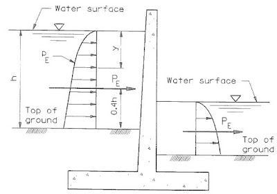
The above figure indicates the variation of water due to the earthquake. This pressure shall be added to the static pressure to find the final loading.
The article water pressure due to earthquake could be referred for more information on the forces acting on a dam due to pressure load calculations.
Wind Pressure
Generally, the wind pressure is not considered for the dams.
When the dam is filled, a very high lateral load than the wind load will be applied to the dam.
However, there is a portion of the dam exposed to wind beyond the full supply level. If required, we can consider that hight for wind load application.
Silt Pressure
Silt deposits are inevitable in reservoirs. They reduce the depth of the dam and water storage.
In addition, it becomes a burden to the dam too.
With the time when there are floods, silt moves into the reservoir.

The submerged pressure applied by the silt can be calculated as shown above figure.
P = kaγ’h
where, ka – active earth pressure coefficient, γ’ – submerged density of silt, and h – height of the silt deposit.
Force can be calculated as follows.
F = 0.5kaγ’h2
Since the silt pressure is additional pressure applied to the dam, it shall be kept in mind to consider when design. Silt could make a considerable effect on the dam’s overturning factor of safety if the dam venerable to have higher silt fill height.
Therefore, a special assessment shall be made to know the forces acting on a dam due to silts.
Thermal Loads
Thermal loads are very critical for concrete dams.
During the construction and after the construction effect to the temperature variations shall be monitored. If it exceeds the limiting values, there will be issues in durability of concrete.
The rise of the concrete due to the heat of hydration shall be limited in concrete structures to avoid cracking. The article, Methods of Limiting Temperature of Concrete could be referred for further information.
Further, attention shall be drawn on thermal cracks due to the variation of concrete temperature. The article, Thermal Cracking of Concrete provides comprehensive information on this subject.
The following combination of loading shall be considered when the design for the crack width of the concrete.
- M + T+ T2
- T1 only
- T1 + T2
Where,
M – Bending Moment
T – Tension Force
T1 – Rise of temperature from ambient due to heat of hydration
T2 – Seasonal variation of temperature from ambient temperature
Impounding Stresses
The impounding of a dam is filling it for the first time.
Impounding is very critical for rockfill dams, earth dams, or similar types of dams.
When the water level rises, there will be stresses in the core with the saturation.
Therefore, there are limitations in the rate of filling. It could depend on the specification of the project.
It shall be allowed to gradually raise the water level in the reservoir.
Ice Pressure
In countries where there is variation in temperature due to seasonal effects. Water becomes ice.
When they melt and expands a pressure will b applied to the dam.
It could be in the range of 250 – 1500 kN/m2
Self-weight
The self-weight of the structure need to be taken into account when it designs of stability in serviceability limit state and ultimate limit state design.
It is very easy to calculate the self-weight of a concrete dam. It is the density of concrete multiply by volume of concrete.
However, when we need to calculate the weight of the rockfill dam, more effort is required as there are different types of layers with different densities.