All About Shear Wall [Design Considerations]
You want to know all about the shear wall read this article from top to bottom. The shear wall is an inevitable element in tall buildings. Let’s discuss the concrete shear wall and shear wall design.
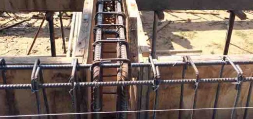
The shear wall is a concrete wall constructed from the foundation level to the top of the building. The thickness and the length of the walls are determined as per the design requirements. Typically, shear walls are constructed as lift core walls and around the staircases.
Use of Shear Wall
Why we use shear walls?
It is not that difficult question to answer.
We construct shear walls to maintain the stability of the structural systems against the lateral loads. The shear wall along or together with other structural elements carry the lateral loads applied to buildings.
The articles Lateral Load Resisting Systems and 14 Types of Structural Forms for Tall Buildings discuss in detail about the available structural systems to resist the lateral load on buildings.
Generally, a rigid frame structure can be used to resist the lateral loads up to 15-20 stories without getting the support of the shear walls or without construction shear walls in that building. However, with the increase of the height of the building, lateral loads become critical
Therefore, we need to have shear walls to resist the lateral loads. The shear wall can provide resistance for lateral loads about 35 stories.
Once the shear wall contributed to the lateral stiffness of the building, it reduces the lateral deflection of the building considerably. There is a limitation of the drift of structures to maintain human comfort in a building.
More the selection of the structure, it could affect the nonstructural elements. They could crack if it exceeds the allowable limits.
Allowable lateral deflection of building = height /500
Allowable drift = 1/500
These values could vary from standard to standard. However, they could not vary significantly.
Where Should Locate Shear Walls?
As discussed previously also, the majority of the shear walls are constructed as core walls of the lift and around the staircases.
During the initial design stage of the project, structural engineers’ content shall be taken by the when locating the shear walls or the lift core walls as they made a considerable impact on the behavior of the structure.
When the lateral loads are applied to a structure when they are taken by the shear walls, the eccentricity of the loading leads to rotating the structure. This is identified as the torsional behavior of the structure.
Therefore, most of the time and as much as possible, shear walls are located symmetrically to minimize the rotational movements.
Behavior of Shear Wall Under Lateral Loads
The shear wall along without considering the interaction of the frame can resist the lateral loads of about 35 stories. When the number of floors is increasing shear walls cannot resist the loads along. Further, the length and with of the shear walls also can not be increased due to the limitations in the floor area.
In these situations, we consider the interaction of the shear wall with the frame is considered. Reduces the lateral deflections/drift considerably. Further, it reduces the flexural moment in the wall considerably.
Therefore, consideration of the wall frame interactions improves the performance of the structure and it reduces the cost of the construction too.
Coupled Shear Wall
Connecting two shear walls located apart by a flexural element increases the lateral stiffness of the building. In high rise buildings, generally, there are two lift cores connected by a lobby that can be observed. Further, they are aligned usually as shown in the following figure
All the aligned shear walls can be connected by flexural elements. Thus, significant improvement of the lateral stiffness can be achieved.
It reduces the lateral deflection and the floor drift indexes considerably. Further, the reduction of the core bending moment also can be achieved.
The above figure clearly indicates the reduction of the bending moment of the shear wall. Further, it appears that there is a significant drop in the bending moment with the coupling action.
Shear Wall Design
Firstly it is required to calculate the different types of loads on the shear walls.
The following steps can be followed in designing the shear walls.
- Calculate the lateral loads to be applied to the structure. Lateral could be wind loads or earthquakes loads.
- Depending on the analysis method lateral loads could be applied. If the shear wall design is done without considering the wall frame interaction, the manual calculation can also be used to analyze the shear walls
- In this method, the lateral load shall be applied on each wall based on their stiffness. That means the total load shall be divided amount the walls based on their stiffness. A computer base analysis could also be done to verify the analysis results.
- If wall frame interaction is considered, the analysis could be done by computer-based software. It would be more convenient than manual calculations. The lateral load could be applied manually to the analysis model or it could be allowed to software to generate the lateral load by itself.
- Relevant vertical loads that could be transferred from the beams and slabs connected to the shear wall shall also be considered in the analysis.
- After doing the analysis, we can calculate the bending moment or axial stresses at the foundation level.
- Shear walls are designed to resist the stresses of the in-plane action. Out of plane bending is usually omitted and also the out of plane stiffness is not in the analysis.
- We calculate the stresses as indicated in the above figure. If we know the stresses, we can calculate the required area of reinforcements as the yield strength also known.
- Most of the time there will not be a requirement of providing reinforcement to carry the tensile stress. Vertical loads applied on the wall balance the tensile stresses due to the bending action. Further, shear walls are planed in such a way that it has considerable axial fore for economical design.
- If the whole section is compression and it is with the allowable limit that concrete can carry, we may only provide the minimum reinforcements. On the occasion where the compressive stress is exceeding the acceptable limit, we could provide reinforcements base on the requirement.
- In addition to the above, there are concerns about the slenderness of the shear walls. Base on the lateral support, it could be checked with relevant standards.
Shear Wall Reinforcement Detailing
Most of the shear walls are detailed with the conventional method. However, when the later lateral loads are increasing or if they are subjected to cyclic loadings, special detailing techniques are sued.
According to the guidelines of Eurocode 2, Folliwngs are considered in the reinforcement detailing.
- Vertical reinforcement: 0.002 Ac (half placed in each face) and the minimum diameter of the bar is 12mm
- Horizontal reinforcement(in each face): 25% of the vertical reinforcement or 0.001Ac whichever is greater. The minimum preferred bar diameter is one-fourth of the vertical bar diameter.
- Links: diameter shall not be less than a quarter size of the largest compression bar.
- Maximum area of vertical reinforcement 0.04Ac
- Minimum spacing of bars 75mm. If bar size is 40mm, spacing greater than 100mm)
- Maximum spacing of vertical and horizontal bars: the lesser of 3 times the wall thickness or 400mm.
- Further, any vertical compression bar not close by a link should be within 200mm of a restrained bar.
- Horizontal spacing: maximum spacing should not exceed twice the wall thickness
The following diagram extracted from the Standard Method of Detailing Structural Concrete indicates typical methods that could be used when detailed drawings are prepared.
Failures of Shear Walls
Knowing the structural behavior of shear walls is very important especially when we are designing tall buildings. Shear walls become very critical elements in those buildings.
Failure of a shear wall could fail the lateral load resisting system and as a result collapse of a structure is also possible.
Mainly there are four types of failure modes that can be identified.
- Flexural failure
- Horizontal tension
- Sliding on flexural cracks
- Sliding on construction joint
Providing adequate stiffness to the shear wall with necessary reinforcements detailed correctly could avoid any failures.
Shear Wall Construction
There are key things to be considered at the design stage when the shear walls design.
- The thickness of the shear wall becomes more critical where the workability of concrete is matters. If there are no possibilities in producing good workable concrete, the thinner concrete wall brings trouble to you.
- Further, when the thickness of the wall becomes smaller, concrete pouring is also very difficult. Separation due to the increase of free fall height, etc. could be expected.
- Therefore, when finalizing the thickness of the walls, attention shall be made to the constructability.
Mostly in tall buildings, a shear wall construction is done by using the system formworks that can be fixed and removed very easily. It saves time and costs considerably.


