Uplift pressure is a design load to be considered for the structures constructed below the groundwater table. When the depth of the excavation is deeper, the greater the upward pressure applied by the water.
Knowing how to calculate the uplift pressure is very important for structural engineers as mostly many structures are constructed below the groundwater table.
Let’s see what the structures that we need to consider the uplift pressure.
- Underground tanks
- Basement floor slabs
- Raft foundations
- Dams
- Concrete slabs
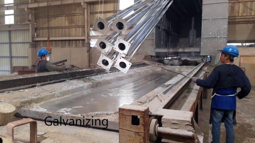
Design of Underground Tanks for Uplift Pressure
A tank constructed below the water table will be floated on the water if we don’t consider the upward pressure by the water. Further, it could lead to structural failure.
The following figure indicates a tank constructed under the ground.

As indicated in the above figure, uplift pressure will be applied to the foundation.
How to Calculate Uplift Force
The pressure at a depth “h”; p
P = hρg
Further, this question can be written as
P = ϒwh
Area of the base slab = A
Uplift Force = ϒwh A
Factor of Safety Against Uplift Pressure
Generally, the factor of safety against uplift is in the range of 1.2 – 1.5. Usually, it is kept at 1.2.
The following procedure could be used to check the uplift.
- Calculate the uplift force as per the above equation
- Calculate the weight of the structure. The weight shall not be the total weight of the structure if stage construction is done without dewatering. In such situations, part of the structure to be constructed in the first stage shall be considered for the weight calculations. If dewatering is done until the structure gains its strength, the total weight of the structure could be considered for evaluation of the factor of safety against uplift.
- The factor of safety against uplift pressure = weight of the structure/uplift force > 1.2
- The base slab should be designed for the pressure applied by the water and soil pressure due to loads from the tank.
Uplift on Basement Floor Slabs
Mostly the basement floors are constructed below the groundwater table. Further, they are constructed in several stages.
Further, there could be several levels in the basements.

Usually, these slabs are designing for uplift forced applied on the basement slab after the construction only. If the area to be built is covered with shorings such as sheet pile walls, secant piles, etc. there will not be water inside the excavation.
However, it is required to consider the water pressure on the basement slab during the operations. Since the basement is fairly deeper, the thicker slab is required to be constructed to bear the applied forces.
In addition, when the basement is deeper, there should an anchoring system to bear the upward force on the basement slab.
When the basement slab is on the rock, it could be supported by the basement rock. However, in some of the structures, the basement slab and the total structure is supported by pile foundations.
When the basement slab and the superstructures is rested on the rock, rock anchors shall be constructed to bear the upward forces.
Further, when the structure is on the piles, piles shall be designed for the tensile forces. Piles shall be designed to bear the axial tensile forces. In addition, the pile shall be socketed in the rock adequately to have sufficient friction.
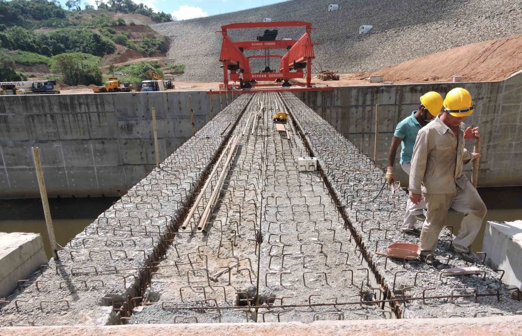
Uplift Pressure in Raft Foundations
Same as other structures, raft foundations are also designed for uplift forces.
However, due to the higher thicknesses of the raft slabs, the uplift forces are not critical especially for the basement constructed to close to the ground.
With the increase of the depth of the basement floors, it may be required to consider the upward pressure on the foundation.
Uplift Pressure on Dams Uplift Pressure on Weirs
Dams are constructed to collect the water for generating electricity, irrigation, using portable water, etc. Further, their design life is more than 120 years or higher due to the importance of the structure.
Further, they are built as rigid structures that can hold any force applied to them.
Usually, the concrete structures are built on the rock. However, there could be occasions where they are built on solid ground.
Even it is built on the rock and rock is grouted to improve its permeability issues, there could be water paths under the foundation.
There are two methods used in designing these structures.
- For fairly lighter structures are anchored into the rock to avoid overturning moment due to the uplift pressures. However, this method has a certain risk as the rock anchors could corrode when it exposed to a corrosion environment for such a long time even though bars are galvanized. Mostly the anchors designed for tensile forces is placed evenly connection the ground and rock.
- The weight of the structure is maintained than that of the uplift pressure. Thus, there will not be any overturning moments.

It required to design the whole structure for the upward pressure applied by the water. As indicated in the above figure, the thickness of the latter part of the structure is comparatively lesser than the ogee area.
There are methods of obtaining the pressure values under the base, which not discussed in this article, shall be used to check for the overturning and structural designs.
Further, the effect of the uplift pressure shall be considered as one of the most important items in the design.
Similarly, the uplift pressure on the retaining walls shall also be considered where applicable depending on the nature of the structure.
Uplift Pressure on Retaining Walls
When a retaining wall is built to retain the liquids and if they are taller, there will be fairly high upward pressure in the retaining wall that could cause failures.
Most of the time during the design, it forgets to consider the uplift pressure on the foundation design.

Though we consider the weight of the water is contributing to the re-store moment in the overturning calculations check, uplift pressure applied on the base in an upward direction generates an overturning moment.
Therefore, we have to be aware of these aspects during the design. Further information available in the article stability calculation of retaining walls on other designs.