It is the common practice of detailing the structures to improve the ductility and to avoid failure due to the cyclic loading. In addition, seismic detailing is done when structures are not designed for seismic load even when they are located in non-seismic zones as a measure to avoid possible risk.
Based on the studies, failure of the structures has occurred due to the failures of joints.
Cyclic loading affects significantly the structural joints as the highest forces are generated at joints.
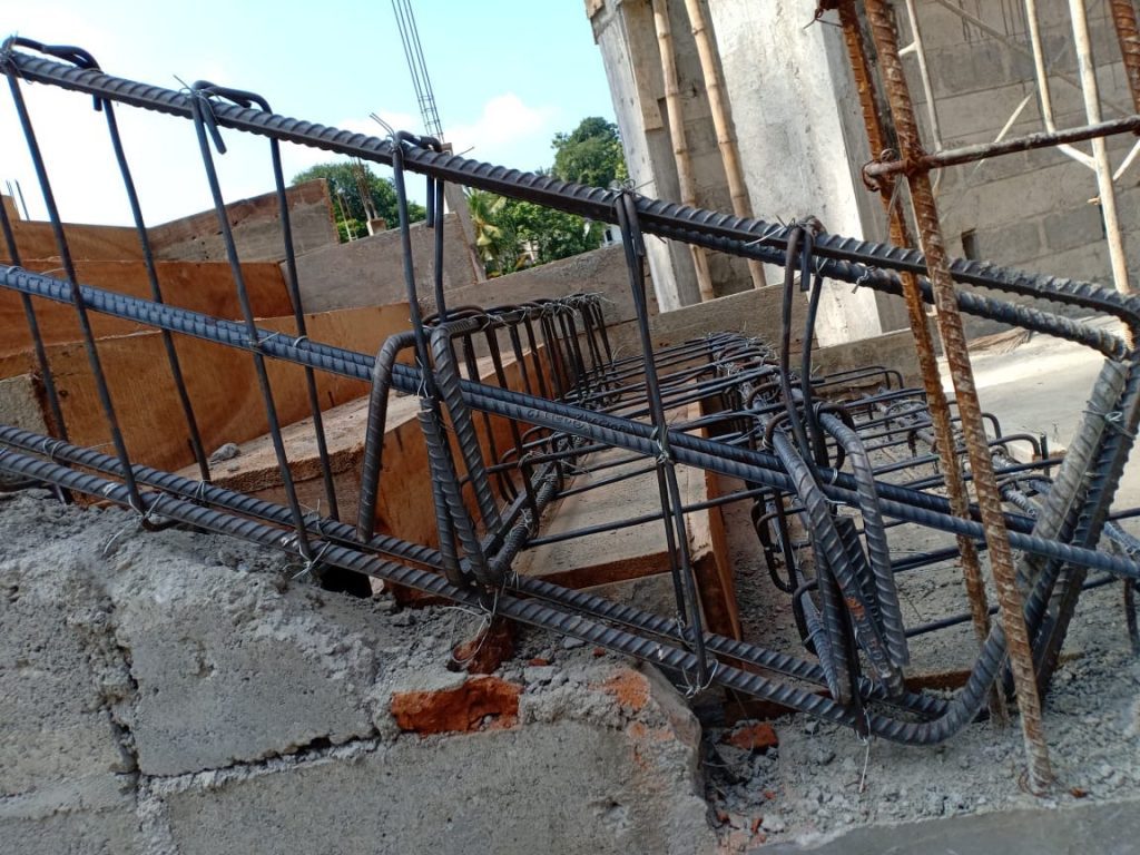
Figure 01 indicates the column failure due to the lack of attention made during the structural detailing.

Failures are mainly caused due to the lack of confinement of structural joints.
Therefore, structural detailing mainly concentrates on the improvement of the confinement near the joints and at joints as part of seismic detailing.
All the design codes and detailing manuals have addressed this issue.
Confinement
Confinement is obtained by providing the links around the reinforcements. There are different methods that can be used to obtain the confinement based on the type of the section.


Reinforcement can be confined as shown in Figure 02 to avoid the failures due to the cyclic loadings. Further, confinement will increase the strains that concrete fails as shown in Figure 03.

Therefore, it is very important to attend the confinement of the longitudinal reinforcements. Considering this aspect, as discussed previously, the reinforcement detailing methods have been introduced.
Beam Reinforcement Seismic Detailing
Confinement zone is defined close to the nodes and the unconfined zones are defined in between the confined zones for reinforcement detailing purpose.
Figure 04 indicates the proposed arrangement by the Society of Structural Engineers Sri Lanka to improve the structural detailing.

According to this guideline, it is recommended not to provide bent-up bars and to avoid lapping close to the supports.
Further, it is recommended to provide 50% as bottom reinforcement at supports in severe seismic zones and it suggests providing 30% in other zones.
The maximum percentage of the reinforcement area is limited to 2% or recommended to follow the BS8110.
More importantly, the guideline recommends proving the shear links at a spacing of 150mm or less at laps. It is recommended to avoid cranking beam reinforcements at columns.
Column Reinforcement Seismic Detailing
Detailing guideline prepared by Society of Structural Engineers of Sri Lanka was referred to get the information on improvement of the confinement of column longitudinal reinforcements.
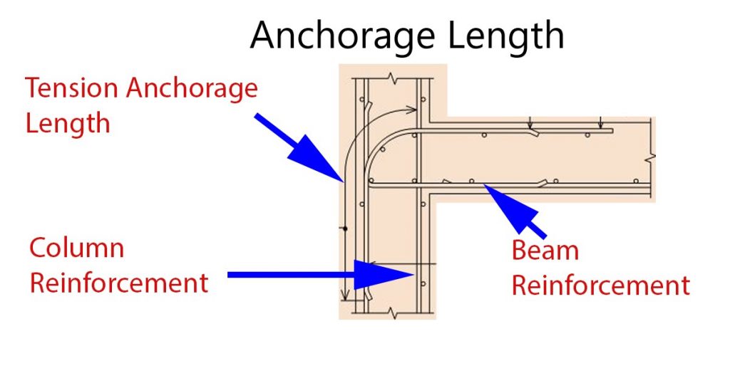
Figure 05 indicates the typical arrangement shown in the guideline.

In addition to the information given in Figure 05, attention was drawn to the following.
- The slope of the column reinforcement within the beam-column joint shall be less than 1/6 (with respect to the vertical) when the size of the columns is reduced. When it is a greater reinforcement shall be terminated. The necessary recommendation given in the guideline shall be followed for anchorage lengths of starters and terminating bars.
- The spacing of the links shall be as indicated in Figure 5.
- Crank length shall be 10 times the bar diameter
- The column vertical reinforcement ratio shall be less or equal 4% and it shall be equal or greater than 1%. It should be limited to 6% at laps
- It is recommended to lap column reinforcement in the central zone.
- If 50% of column reinforcements are lap at the bottom end of the column (laps starting from the floor), lap length shall be equal or greater than 1.25 times general lap length.
- If more than 50% of vertical reinforcement laps at the bottom end of the column, lap length shall be multiply by 1.5.
Stirrups and Ties in Seismic Detailings
It is recommended to bend all the links by 1350 and to have anchorage as mention follows. The length of the hook should be measured from the tangent point.
- Plan bar Links – grater or quals 10d or 100mm whichever greater. Where, d – is the link diameter.
- Ribbed bars – grater or 6d or 80mm whichever grater.
The Wikipedia article Earthquake Engineering is more useful in reading.