Same to the structural analysis and the design, following the reinforcement detailing, is very important in the relation to covering the design and construction requirements.
It is away not the design requirement we shall look into when reinforcement detailing is done. There is a special construction requirement that needs to address. In addition to the rebar detailing rules, the condition of the other elements also needs to be considered as the retail is more complex.
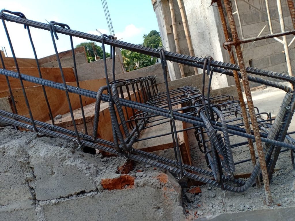
For example, if we are detailing a long-span beam or a section having high reinforcement area connecting the reinforced conjected column, we must consider the reinforcement arrangement of the column to make sure our details can be executed at the site.
With that note let’s see what the detailed rules are to be followed according to Eurocode 2. We are discussing the beam reinforcement detailing according to Eurocode 2 or the EC2
Minimum Area or Reinforcement
Tension Bars
As min ≥ 0.26 [ fctm / fyk] btd > 0.0013btd
where,
fctm to be obtained from Table 3.1 of Eurocode 2
Compression Reinforcement
As min ≥ 0.002Ac
Transverse Reinforcement
As min ≥ 0.0015hfl
here “l” is the span
Reinforcement Bar Spacing
Minimum Bar Spacing
- 75mm allowing sufficient space to insert the poker vibrator
- 100mm for pairs of bars
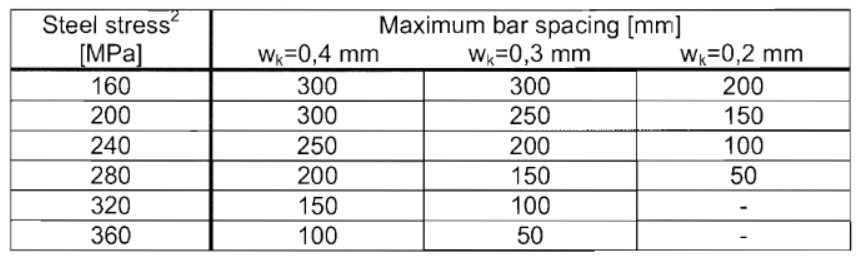
Maximum Bar Spacing – Tension Bars
The following table extracted from the Eurocode 2 indicates the reinforcement bars’ spacing based on the crack width and rebar service stress. The service stress of the reinforcement bare can be considered as 310 Mpa unless otherwise stated.
Maximum bar spacing to control cracks
Maximum Bar Spacing – Compression Bars
- 300mm
- All the compression bars within 150mm spacing are restrained. Othrwise, we provide the link.
Beam Side Reinforcements
- Side reinforcements are provided when the height of the beam is equal to or greater than 1000mm; h ≥ 1000mm
- Rebar needs to be provided between the tension surface and the neutral axis. This implies, roughly half the height from the tension face, needs to be reinforced as side reinforcement.
- 16mm reinforcement bars of spacing equal to or less than 250mm could be provided to crack control as suggested in the Stranded Method of Detailing of Structural Concrete.
- Or we may follow Section 7.3.3(3) BS EN 1992-1-1:2004 Section 7.3.3(3) to calculate beam side reinforcement requirements based on the crack controlling requirements.
Beam Shear Links
Minimum Requirement
Asw / Sbw ≥ 0.085%
where,
Asw – Cross section area of two legs of link
bw – Average width of the section
S – Spacing of link (≤ 15ø of main compression bar)
The preferred minimum link diameter is 8.0 mm
Link Minimum Spacing
100mm or [ 50 + 12.5(no. of legs)] whichever is greater.
Link Maximum Spacing
300mm or 0.75d or 12 times the diameter of the compression bar; whichever is least.
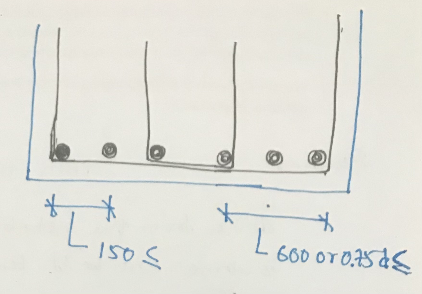
Maximum Lateral Pitch of Links
600mm or 0.75d
The distance to the compression or tension bars from the vatical leg should not be greater than 150mm
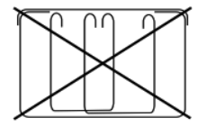
Correct Arrangement of Shear Links
Correct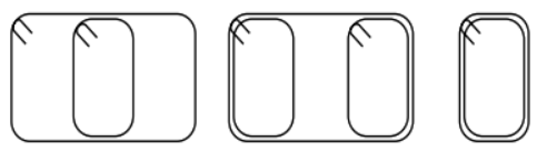
Wrong