In this article were are concentrating on column reinforcement details and the basic requirement to be adopting column rebar detail is prepared.
Column reinforcement details can be developed for normal conditions or seismic conditions. There are significant changes in the column rebar arrangement when it is detailed for seismic.
The article seismic detailing of beams and columns could be referred to for more information on column rebar arrangement for earthquakes.
In this article, we are concentrating on the column reinforcement details as per the BS 8110 Part 01. In addition, some of the information is referred to as Eurocode 2.
Let’s discuss column reinforcement detailing requirements.
- Minimum Reinforcement in Column
The minimum area of reinforcement in the column is 0.4% of the cross-sectional area of the column as per BS 8110.
100As / Ac = 0.4
- Maximum Reinforcement in Column
The maximum area of reinforcement of columns is as follows. The below values are calculated as a percentage of the gross cross-sectional area of concrete.
-
- Vertically cast column 6%
- Horizontally cast column 8%
- Lapps in vertically/horizontally cast column 10%
- Containment Links
The diameter and spacing and the number of links per section shall be decided based on the following guideline.
-
- Link Diameter: at least one quarter the size of larges compression bar or 6mm, whichever grater.
- Link Spacing: Maximum spacing shall be 12 times the smallest compression bar.
- All the column reinforcements should have at least one link passing them.
- No rebar in the column should be further than 150mm from the restraining bar. That is if a reinforcement bar spacing is more than 150mm from the restraining bar, that bar needs to be restrained with a link.

- Lapps with Limited Cover
When the diameter of both bars at the lap exceeds 20mm and the cover is less than 1.5 times the size of the smaller bar, transverse links shall be provided throughout the lap length.
At the lap, at least link diameter one quarter the size of the smaller bar. Link spacing shall not exceed 200mm
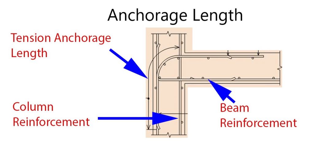
- Design Compression Lap
Compression lap length should be at least 25% greater than the compression anchorage length.
The lap length of columns could be referred from Table 3.27 of BS 8110 Part 01.
In addition to lapping, mechanical couplers could be used instead of normal laps.
- Cranking Reinforcement
The minimum slope of the crank is maintained at 1:10. However, this value may be increased up to 1:20 for smooth load transferred.

Shear links could be provided at the crank to avoid the development of internal tensile stresses. They may be spaced at 75mm as indicated in the following figure. This is one of the best column reinforcement details to be implemented.

- Laps and Link Arrangement – as per Eurocode 2 – IStrucutE
Shear links need to be provided within the foundation and some tolerances shall be allowed for construction work.

- Reinforcement Arrangement When Column size Reduce – as per Eurocode 2 – IStrucutE


For further information, relevant code shall be referred to. This article on column reinforcement details is based on the detailing rules specified on BS 8110 Part 01 and some of the sketches are obtained from the Standard Method of Detailing Structures by IStructE.