Slab reinforcement details should be done by following the relevant code of practices and standards method of detailing of reinforcements.
Mainly, there are three types of slabs in cast-in-situ concrete.
- One way spanning slabs
- Two-way spanning slabs
- Cantilever slabs
In general, there are similar requirements for one-way, and two ways slab when slab reinforcement detail drawings are prepared.
Let’s discussed the design code requirement specified for slab reinforcement details.
The following slab reinforcement arrangements are specified in the BS 8110 Part 01.
- Minimum Percentage of Reinforcements
Provide reinforcement area of 0.13%. ( 100As/Ac = 0.13)
- Anchorage of Bars at a Simply Supported End
If the desing ultimate shear stress at the face of the support is less than half the appropriate Vc, a straight length of bars beyond the centerline of the support equal to either one-third of the support width or 30mm, whichever is the greater.
- Spacing of Bars
The clear spacing of bars shall not exceed lesser of 3d or 750mm, where, d is the effective depth.
The detailing rules could also be applied as per Eurocode 2.
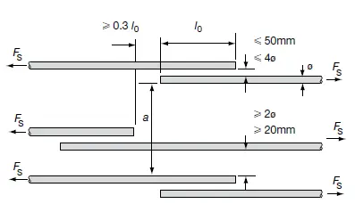
As indicated above, spacings for laps shall be followed and the gap between the lapping bars shall not be less than 50mm or 4∅ whichever lesser. Here, ∅ is the bar diameter.
- Crack Control – when crack widths are not checked by calculations No Further Checked Required
a) Slab depth does not exceed 250mm when the steel grade is 250
b) Slab depth does not exceed 200 mm when the steel grade is 460
c) Slab reinforcement percentage less than 0.3% (100As/bd < 0.3%
When above a, b, and c conditions do not apply, bar spacing shall be limited as following Table (Table 28 of BS 8110 Part ) where the reinforcement percentage exceeds 1% or the values given in Table 28 divided by the reinforcement percentage for lesser amounts.
![]()
- The spacing of Shrinkage Reinforcements
Slab reinforcement details are the same as the wall reinforcements as specified in the Cl 3.9.4.19 in the BS 8110.
Provide 0.25% of the concrete crossectional area for Grade 460 steel.
- Simplified Rule for Slab Reinforcement Details
The simplified rules can be applied when slab reinforcement detail drawings are prepared when the following condition is met.
-
- The slab is designing for uniformly distributed loads
- In continuous slabs, design loads are approximate equal
The following figure is taken from BS 8110 for reference.
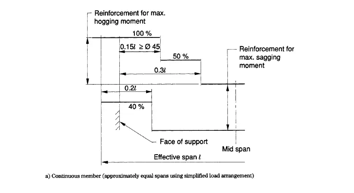
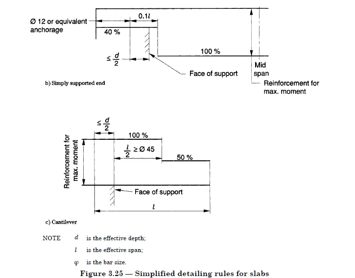
According to the above detail in the BS 8110, slab to reinforcements need to extend 0.3 x span(from the face of the support) for continuous support. However, 100% area of steel needs to be continued up to 0.15 x span.
This can be achieved by an alternative bar arrangement as indicated in the following figure.
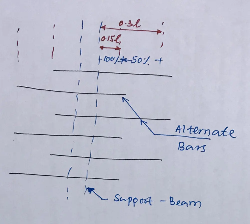
Otherwise, as an average, we could continue the top reinforcement 0.25 x span (from the face of support). This is not indicated in the guidelines, but we could consider doing it for simplicity.
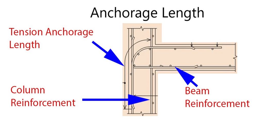
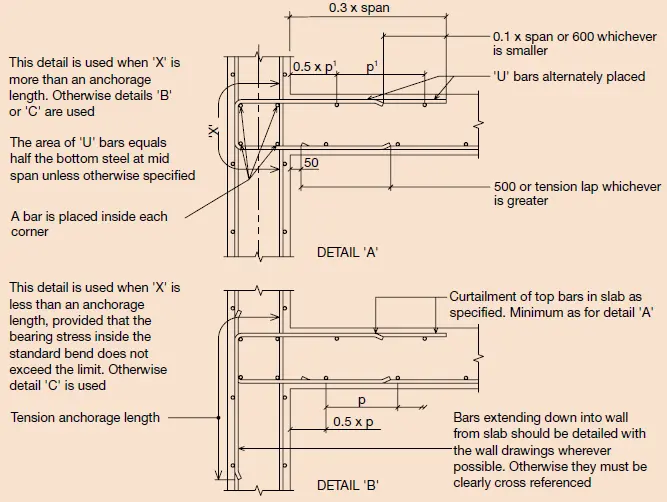
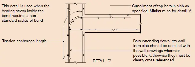
- Slab Reinforcement Details at Restrain Edges
The reinforcement arrangement is as per the Standard Method of Detailing Structures by IStructE.
Tension anchorage lengths and additional reinforcement bars at the restrain edge are indicated in the following details.
Further, the following details are relevant to Eurocode 2.
The article slab design could be referred for slab reinforcement design aspects.