Beam reinforcement details shall be done in accordance with relevant standards methods of detailing. There are different guidelines developed in addition to the code of practices, we could refer to beam reinforcement are detailed.
In this article, we are concentrating on the standard method of beam reinforcement details.
Firstly, we check the detailing rules specified in the BS 8110 Part 1.
The following list of requirements shall be checked when reinforcement drawings are prepared.
- Minimum percentage of tension reinforcement – 100As/ Ac = 0.13 for a rectangular section when fy = 460N/mm2
- Minimum compression reinforcement – 100As / Ac = 0.4 (where such reinforcement is required for the ultimate limit state; fy = 460 N/mm2)
- The maximum area of beam reinforcement – Tension or Compression R/F shall not exceed 4% Ac
- Links for containment for beams compression reinforcement – at least one quarter the size of the largest compression bar or 6mm whichever is the grater (where compression reinforcement required for ultimate limit stage desing)
- Maximum spacing of links – 12 times the size of the smallest compression bar
- Arrangement of the links for containment of beam compression reinforcement – No bar within the compression zone should be further than 150mm from the restrained bar. (where compression reinforcement required for ultimate limit stage desing)
- Beam side reinforcement – Provide when depth exceeds 750mm and provide 2/3 height measured from tension face. The maximum spacing shall not exceed 250mm. Minimum bare diameter less than √( sbb / fy) where sb is the bar spacing and b is the breadth of the section or 500mm if b exceeds 500mm.
- Clear distance between bars in tension –No longitudinal tension bar is more than 150mm from the vertical leg of the link.
- The maximum amount of reinforcements in a layer including tension laps – the sum of reinforcement sizes in a particular layer should not exceed 40% of the breadth of the section at that level.
The above detailing rules shall strictly be followed when beam reinforcement details are prepared.
In addition, there are other requirements specified in the Standard Method of Detailing Structural Concrete by IStructE.
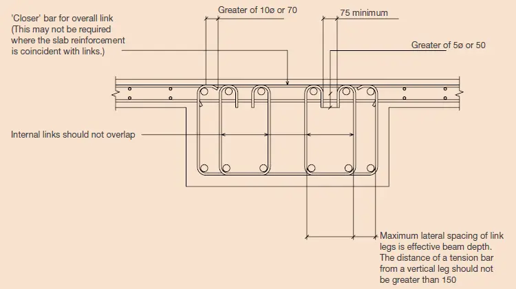
Typical arrangement of links
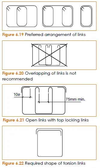
Link arrangement in the cross-section
Typical Reinforcement Curtailment in a continuous Beam Reinforcement Details
-
- Provide 100% required top steel area(hogging R/F) up to length 0.15l (≥∅ 45) where l is the effective span
- Provide 60% beyond that up to 0.25l from the face of the support
- Beyond that point provide 20% of steel area from required tension-steel as hanger bars.
- Provide 30% to support from the maxim sagging reinforcement.
Generally, it is a bit difficult to curtal reinforcement as above detailing rules. The simplest method is to provide hogging reinforcement 0.25 span and then provide hanger bars (20%).
The typical detailing rule cannot be applied to all situations. Mose suitable method is to do the reinforcement detailing as per the bending moment variation.
The guidelines given in the article curtailment of beam reinforcements could be followed for the method of curtailment of the top reinforcement.
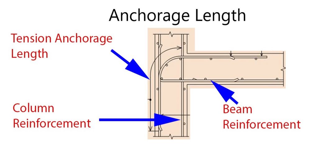
Anchorages in Beam Reinforcement Details
There are two types of anchorages namely tension anchorage length and compression anchorage length. The tension anchorage length is more critical in the beam reinforcement at supports. The following arrangement shall be followed.
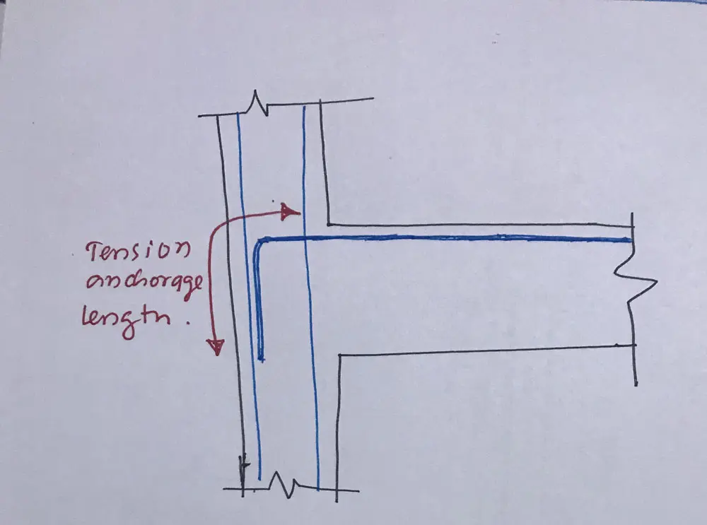
The tension anchorage length shall be calculated from the restraining bar. Here the restrain bars are the column reinforcements.
When it is required to continue the top beam reinforcement below the beam bottom to maintain the tension anchorage length, column construction joint need to lower from beam bottom or U bars shall be provided while maintaining column construction joint at beam bottom level.
The article design anchorage bond stress could be referred for calculating method of anchorage length.
Beam Hanger Reinforcement at Beam to Beam Join
When one beam is supported by another, the vertical force applied to the supporting beam by the hanging beam.
It is required to provide reinforcement to carry this axial force. There are different guidelines to calculate the area of the reinforcements.
The article Hagger reinforcement bars could be referred for the method of calculating the area of reinforcement with a worked example.