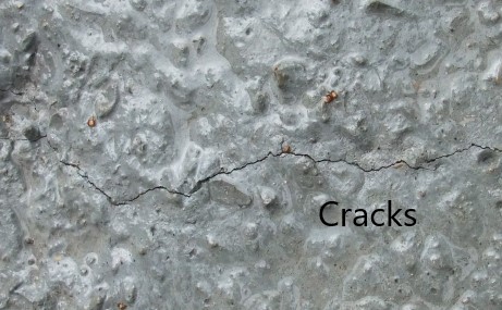
Early thermal cracking of concrete is inevitable if we don’t take necessary actions during the design and the construction. Both stages have a significant impact on the cracking of concrete.
In this article, we are concentrating on the shrinkage and thermal movement of the immature concrete.
Immature concrete does not have the adequate strength to resist the tensile stresses developed in the concrete. As a result, concrete is cracking.
What are the early thermal cracks?
Early thermal cracks occur in concrete due to the lateral restrain. During the heat of the hydration process, the heat dissipates through the surface and the concrete surface subjected to thermal movements. It leads to the cracking of concrete.
In addition, the drying shrinkage could also be a reason to appear cracks in the concrete surface.
How to avoid cracking of concrete?
The easiest way is to protect the concrete to avoid the variation of temperature in the concrete surface.
Different methods that could be used to cover the concrete surface could be adopted.
In addition, we can provide reinforcement to resist the tensile stresses developed in the concrete.
Based on the restrain condition, it is possible to calculate the required area of reinforcement to control the cracking of concrete.
Calculate Reinforcement Required to Shrinkage and Thermal Movement in the Immature Concrete – R/F for Thermal Cracking
The calculation is done as per the guidelines given in the BS 8007.
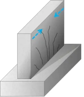
Let’s do it with a worked example – early thermal cracking
Design Date for Worked Example Early Thermal Cracking of Concrete – Concrete Wall
- The thickness of the wall – 300mm
- Consider restrain factor between the wall and the base as; R = 0.5
- Rise of the temperature beyond the ambient temperature due to the heat of hydration: T1 = 400 C
- Variaion of Ambient temperature T2 = 100 C
- Concrete Grade 35A
- Steel fy = 460 N/mm2
Critical steel ratio, ρcri = 0.0035 from Table A1
According to Figure A1,
ρ = As / bh’ where, h’ – depth of the surface zone and ρ – reinforcement ratio
Since h = 300 < 500, depth of surface zone can be taken as
h’ = 300/2 = 150mm.
Note: When the section thickness is greater than or equal to 500mm, the depth of the surface zone shall be taken as 250mm
Therefore, the reinforcement area,
As = ρ x bh’ = 0.0035 x 1000 x 150 = 525 mm2 per meter
According to the Cl A3 of BS 8007, the maximum crack width can be estimated as
Wmax = Smax R α (T1 + T2)
T1 = 40o C
T1 = 10o C
α = 10 x 10-6 /oC
R = 0. 5 Full restrain by base
Wmax / Smax = 0.5 x 10 x 10-6 x (40 +10) = 2.5 x 10⁻⁴
Wmax = Smax x 2.5 x 10⁻⁴
From Section A 3
Smax = (fct/fb) x ( φ/2ρ)
where,
fct/fb = 0.67 from Table A1 for deform type 2 bars.
Combining two equations,
Wmax = (fct/fb) x ( φ/2ρ) x 2.5 x 10⁻⁴
ρ = (fct/fb) x ( φ/2) x 2.5 x 10-4 / Wmax
Consdier 12mm bars and crack width as 0.2mm
ρ = (0.67) x ( 12/2) x 2.5 x 10-4 / 0.2 = 0.005 > ρcri = 0.0035
The area of reinforcement to be plane in both surface zones can be calculated as
As / bh’ = 0.005
As = 0.005 x bh’ = 0.005 x 1000 x 150 = 750 mm2 /m
Provide T12@150 mm
This reinforcement to be provided in the each direction.
This area of reinforcement shall be provided for the section whether its other reinforcement requirements such as bending reinforcement are less than the area of reinforcement required to resist shrinkage and thermal movement.
The following articles could read for more information.