The concrete beam is one of the basic elements in a structure. Concrete columns and concrete slabs are the other most frequently used element in building construction.
There are other types of beams in addition to the concrete, used in the construction. The article types of beams could be referred to for more information on different types of beams.
There are different categorizations for reinforced concrete beams. They can be categorized as follows.
- Rectangular beam
- Flange beam
Other types of categorization could be considered as
- Reinforced concrete beams
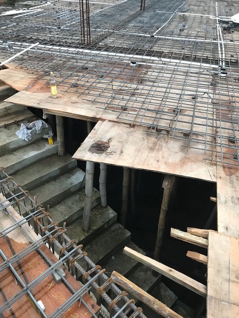
- Precast concrete beams – with beam reinforcement
- Prestress beams – (Post tension and pretension)
Before designing the concrete beam, initial sizing is done to prepare the concrete outline drawings. Initial sizing is done based on the span to depth ratio.
It makes it easy to select a suitable size beam for analysis and design.
How to analyze concrete beam to find Beam reinforcement
The following steps could be followed when analyzing a concrete beam.
- Calculate the loads from the slab (dead loads and live loads)
- Calculate the load from walls – which are on the beam
- Create load combinations.
- Consider alternative load when there are variations in the spans and loads.
- Analysis of the beam could be done by manual calculations or from the software.
- Moment redistribution is done as required and within the allowable limit of the relevant standard.
Design of Concrete Beam
The concrete beam needs to desing for ultimate limit state and serviceability limit state.
Initially, we desing the beam for the ultimate limit and find the beam reinforcements.
Then we check for the serviceability limit state. Under the serviceability limit state, we check the beam for deflection and for cracking.
In addition, attention shall be made to the over reinforcing of the section and under reinforcing of section.
Over Reinforcement
Providing more reinforcement than that required by the desing is over reinforcement. It leads to reduce the strain of the steel and it delays the yielding or reduces the yield strain of the steel. However, the concrete strain will increase.
Failure of the concrete leads to the sudden collapse of the structure without warning. When reinforcement yield, more warnings will be provided.
Cracking of beams, excessive deflection, etc gives us a warning of collapse.
Under Reinforcement
Providing inadequate reinforcement for the section is the under reinforcements.
In these situations, reinforcements lead to excessive deflection and cracking of the structure.
Concrete Beam Reinforcement Detailing
There are requirements for dealing of concrete beams.
All the detailing rules shall be done as per the relevant standards.
Some of the important detailing rules stipulated in the BS 8110-1-1997 as follows.
- Minimum percentage of reinforcement for a rectangular beam when fy = 460N/mm2
100As/ Ac = 0.13
- Minimum compression reinforcement (where such reinforcement is required for the ultimate limit stage; fy = 460 N/mm2)
100As / Ac = 0.4
- Maximum area of beam reinforcement
Neither the area of tension reinforcement nor the area of compression reinforcement should not exceed 4% of the cross-sectional area of the concrete.
- Links for containment for beams compression reinforcement (where compression reinforcement required for ultimate limit state desing)
Links – at least one quarter the size of the largest compression bar or 6mm whichever is the grater
Maximum spacing – 12 times the size of the smallest compression bar
- Arrangement of the links for containment of beam compression reinforcement (where compression reinforcement required for ultimate limit stage desing)
No bar within the compression zone should be further than 150mm from the restrained bar.
- Beam side reinforcement
Side reinforcement shall be provided when the depth of the beam exceeds 750mm.
The maximum spacing sidebars shall not exceed 250mm
They shall provide for 2/3 height of the beam depth measured from the tension face.
The minimum size of the bar shall be less than √( sbb / fy) where sb is the bar spacing and b is the breadth of the section or 500mm if b exceeds 500mm.
- Clear distance between bars in tension
No longitudinal tension bar is more than 150mm from the vertical leg of the link.
- The maximum amount of reinforcements in a layer including tension laps cl 3.12.8.14
At laps, the sum of reinforcement sizes in a particular layer should not exceed 40% of the breadth of the section at that level.
Concrete Beam Reinforcement Desing – Worked Example BS 8110 1 – 1997
Desing Data
- Simply supported Beam
- Dead load 20 kN/m
- Live load 10 kN/m
- Beam span 6m
- Width of the Beam 300mm
- Depth of the beam 500mm
- Characteristic strength of concrete 25 N/mm2
- Characteristic strength of steel 460 N/mm2
Ultimate desing Load = 1.4 x 20 + 1.6 x 10 = 44 kN/m
Ultimate bending moment = wl2/8 = 44 x 62 /8 = 198 kN/m
Calculate effective depth
Assume bar diameter 20mm, links 10mm, cover 25mm
Effective depth = 500 – 25 – 10 – 20/2 = 455 mm
K = 0.128
K < K’ ; no compression reinforcement required.
Z = 377.2 mm
M/bd2 = 3.188 N/mm2
100As/bd = 0.880
As = 1201 mm2
Desing shear force = 44 x 6 / 2 = 132 kN
Shear stress = V/bd = 0.733 N/mm2
Shear Capacity = Vc = 0.606 N/mm2
V < Vc + 0.4 = 0606 + 0.4 = 1.006 N/mm2
Provide Nominal shear links.