The method of beam design for torsion with worked example is debussed in this article. There are basic steps to be followed same as the beam longitudinal reinforcement design.
In the beam design for torsion, torsional link requirements and an additional area of reinforcement to be added to the longitudinal reinforcement are calculated.
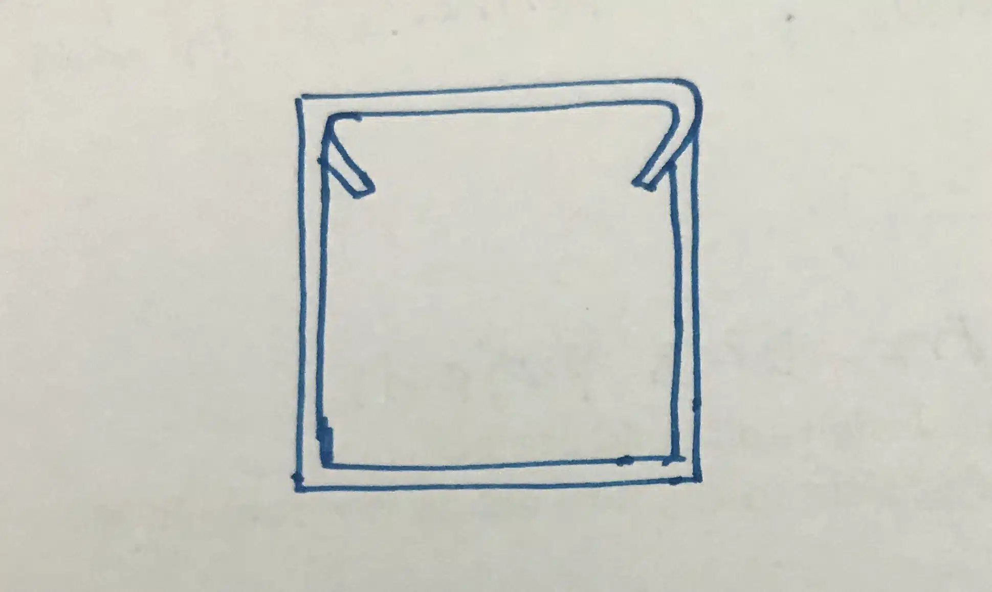
More importantly, torsional reinforcement links are not the same as the usual shear links provided for the beams. The torsional links terminate at two ends not like the conversational link.
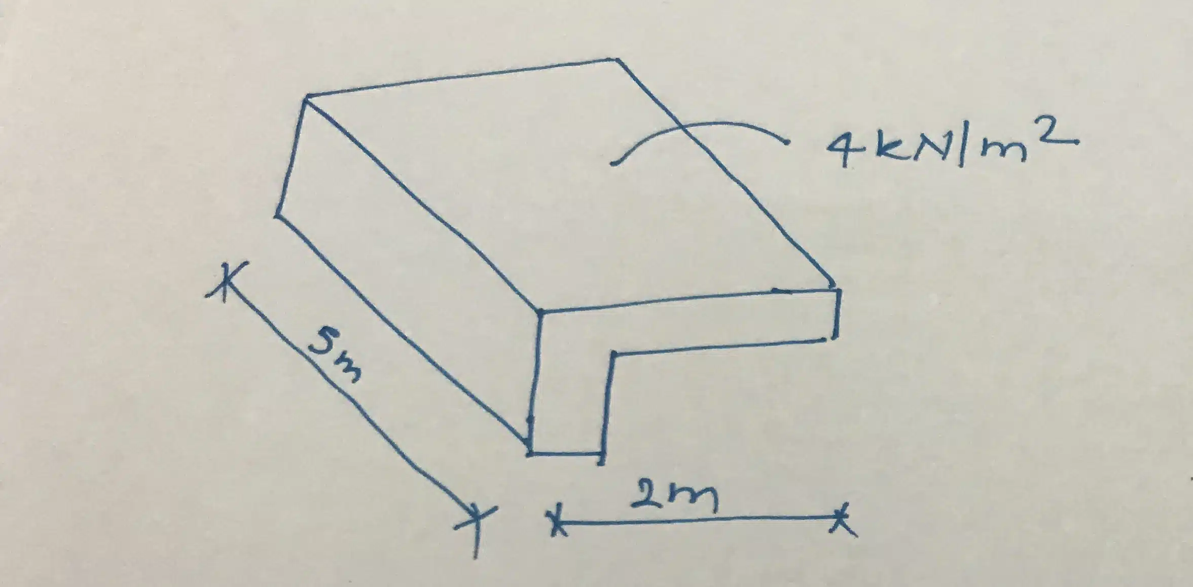
Worked Example Beam Design for Torsion
- Span of the beam = 5m
- Span of cantilever = 2m
- Height of the beam = 600mm
- Width of the beam = 300mm
- Shear link diameter = 10mm
- Cover to reinforcement = 25mm
- Design load on beam including all load factors = 4 kN/m2
- Grade of concrete C30
- Characteristic yield strength = 460 kN/m2
Calculation of Torsional Bending Moment
Bending Moment = 4 x 2 x 5 = 40 kNm
Bending moment per support = 40 / 2 = 20 kNm
Calculation of Torsional Shear Stress, vt
vt = 2T / [ hmin2 (hmax – hmin/3)]
T = 20 kNm, hmin = 300, hmax = 600
vt = 2 x 20 x 106 / [ 3002 (600 – 300/3)] = 1.24 N/mm2
From Table 2.3 of BS 8110 Part 2,
vt min = 0.36 N/mm2 and vtu = 4.38 N/mm2
vt min < vtu and vt > vt min, Therefore, torsional reinforcement needs to be provided.
In this worked example, we are not going to design the beam for shear and bending. However, we need to know the shear stress and shear capacity of the beam for this design. Thus, let’s assume some values for shear stress.
Say, v = 0.25 N/mm2 and v < vc
There are two segments in the beam based on the shear and torsional reinforcement requirement.
- vt ≤ vt min Nominal shear reinforcements are adequate and no beam design for torsion required.
- vt > vt min Design for torsional shear links.
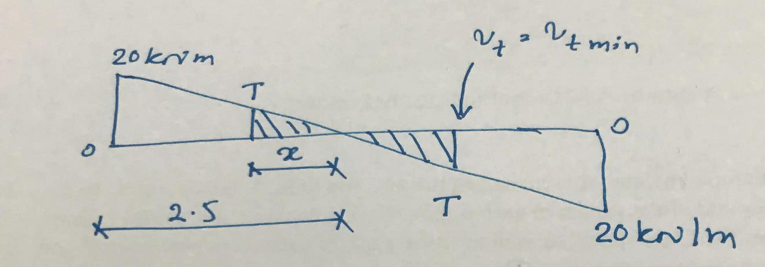
We can easily calculate the segment that we need only the nominal shear links.
First, let’s calculate the torsional moment that specified the minimum requirement for torsional links.
T = vt min hmin2 [(hmax – hmin/3)]/2
T = 0.37x 3002 [(600 – 300/3)]/2 = 8.33 kNm
Now let’s calculate the distance to this moment
Say it is x,
x = (8.33/20) x 2.5 = 1.0 m
Thus, we need to provide torsional links up to 1.5m distance from each support.
Calculation of Nominal Shear Links
Asv / Sv ≥ 0.4b / 0.95fyv
Consider T10 bars = 78 x 2 = 157 mm2 * two legs, therefore, rebar area multiped by 2; ( 78 x 2).
Sv ≤ 157 x 0.95 x 460 / (0.4 x 300) = 575 mm
Provide nominal shear links T10@250mm spacing. This satisfies the minimum shear links requirement also.
Calculate Design Torsional Reinforcement
Asv / Sv = T / [ 0.8x1y1(0.95fyv)]
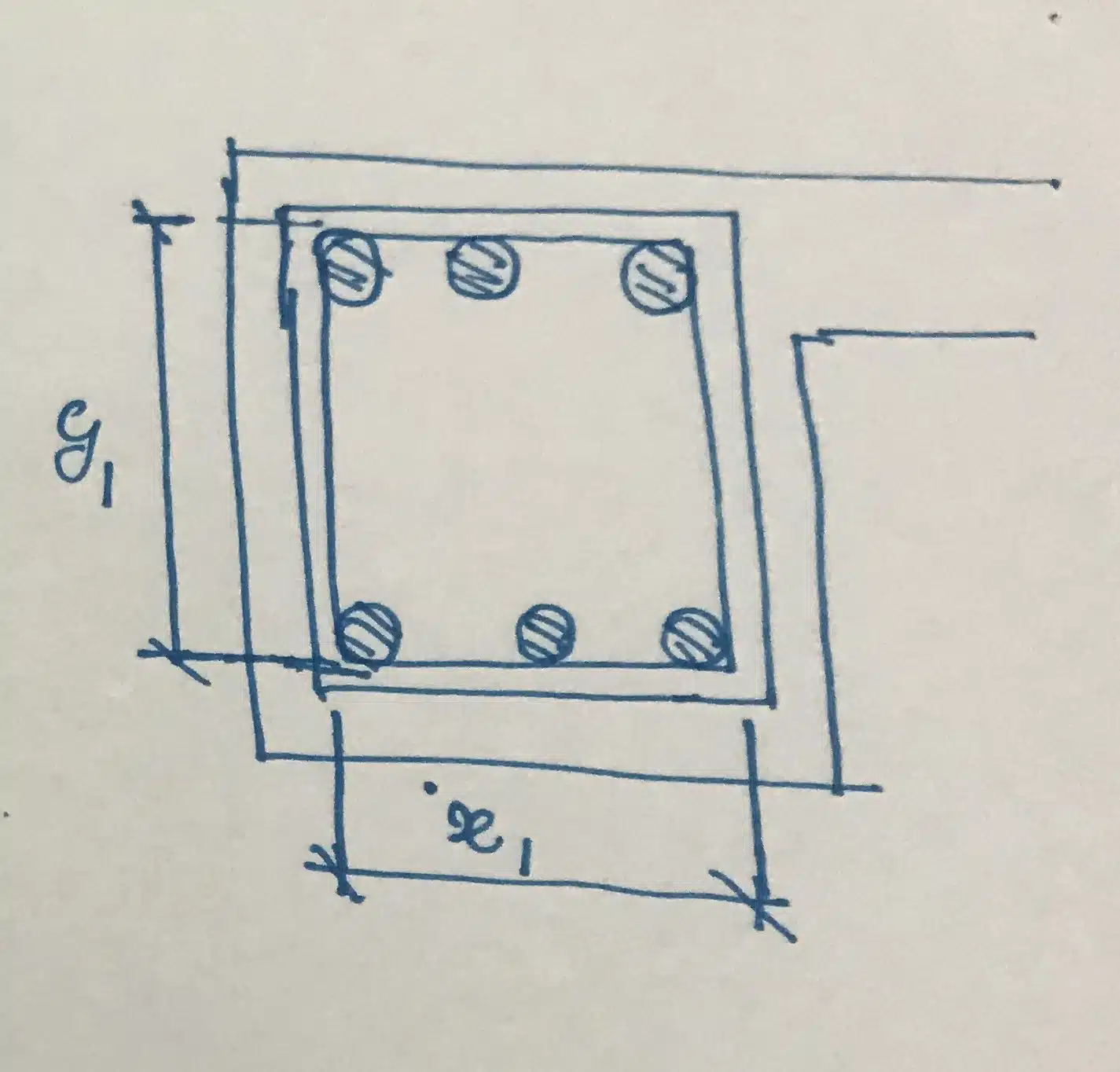
x1 = Smallest center-to-center distance of shear links
x1 = 300 – 25 – 10/5 = 230 mm
x1 = Largest center-to-center distance of shear links
x1 = 600 – 25 – 10/5 = 530 mm
Sv ≤ 157 x 0.8 x 230 x 530 x 0.95 x 460 = 334 mm
Provide torsional reinforcement, torsional shear links T10 @ 200 spacing
Calculation of Additional Longitudinal Reinforcement
The following equation given in the BS 8110 Part 2 can be used.
As = Asv fyv [ x1 +y1)] / Sv fy
As = 157 x 460[ 230 +530)] / (334 x 530) = 358 mm2
This area of reinforcement needs to be distributed at the top, middle and bottom.
Since the width of the beam is 300mm, we can provide three bars at the top, two bars in the middle and three bars at the bottom. Therefore, there will be 8 bars.
Area of a bar = 358 / 8 = 44.7 mm2
We may add this area of reinforcement to each top three bars and bottom three bars. In the middle we may provide 2T12.
In addition to this, we have to check the maximum spacing of the torsional links which is 300mm and make sure to provide torsional reinforcement at four corners.
Also, we have to keep in mind that the torsional link is not the same as the normal shear link.