Knowing seismic design principles are very important for a structural engineer. There are very basic things to be considered by the designer during the design process.
Desing and detailing of structures for seismic events is common in nowadays construction. In some countries where they do not close to a plate boundary and not having an earthquake, adopt the seismic mitigation detailing techniques.
However, when designing critical structures such as dams, high-rise buildings, etc. it is observed that a certain magnitude of peak ground acceleration (PGA) is considered.
In this article, we are concentrating on the factors to be considered in seismic design from the preliminary stage to the completion of the design of the structure.
Convert Irregular to Regular for better Seismic Performance
It is advisable to convert the irregular structure to regular structures whenever possible.
This conversion could lead the structures to behave in a simple manner. Further, it will avoid the torsional modes becoming the initial modes.
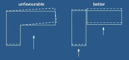
Further, these kinds of separation could be done as per the guidelines given in the relevant code of practices. Especially the gap between the structures shall be maintained within the acceptable limit when separated to avoid collision of the parts.
Adequate Gap between Structures
Ground motion causes the movement of the building in the direction of the seismic waves. Thus, there will be a reflection of the building at the top.
The maximum deflection could be limited during the design as per the serviceability requirement stipulated in the referred code of practice.
Even we are within the limit, if there are two buildings closed by, it is required to check whether there will be a collision between two structures due to an earthquake.
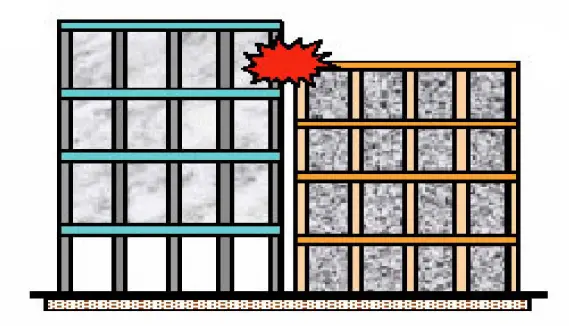
We could calculate the maximum probable deflection, and the required gap shall be maintained accordingly.
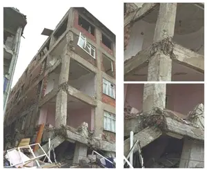
Avoid Soft Storey – Ground Floor
Lateral stiffness of the structure resists the earthquake loads applied on a structure.
Lateral stiffness is provided by the reinforced concrete frame, shear walls, infilled walls, etc.
Variation of the stiffness of the structure over the height (different stiffness in earth floor) affects the lateral loads resisting capacity of the building.
It results in the soft story effect that leads to failures of the structures.
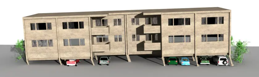
Having a soft story on the ground floor is very critical especially for moment-resisting frame buildings. When there are infilled walls above the ground floor, that portion of the structure has a very high lateral stiffness.
However, on the ground floor, there are only the columns to resist the lateral loads. Therefore, the lateral load resisting system is very weak.
If there are shear walls having the adequate capacity to resists the loads, the formation of soft-story effect will not be observed.
The soft-story may form in the floor above the ground floor too. However, the soft story at the ground floor in a moment-resisting frame building is very critical as the maximum lateral force will be applied to the ground floor.
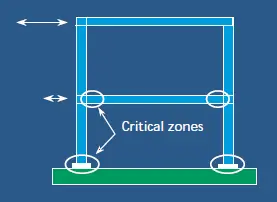
Provide Lateral Bracings Symmetrically
Geometric design or plan is one of the most important factors to be considered from seismic design principles.
Asymmetric bracing causes excessive rotations in the structure as the center of stiffness and the mass are not coincide or not near.
Such deviation causes structural failure and even it could lead to the collapse of the structure in an earthquake.
The following figure indicates the asymmetric lateral load resisting system that do not coincide with the center of made and the stiffness.
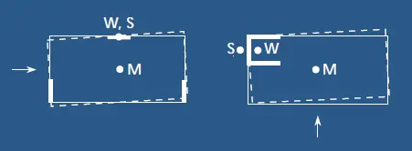
Higher the gap between two centers, the higher the torsional movement of the structure. There will be additional shear forces in the vertical elements which they may not be able to bear. As a result, structural failure could occur.
Therefore, we shall locate the lateral bracing or the lateral load resisting systems in a way that the center of mass and the stiffness is coincided to avoid/minimize the torsional movement.
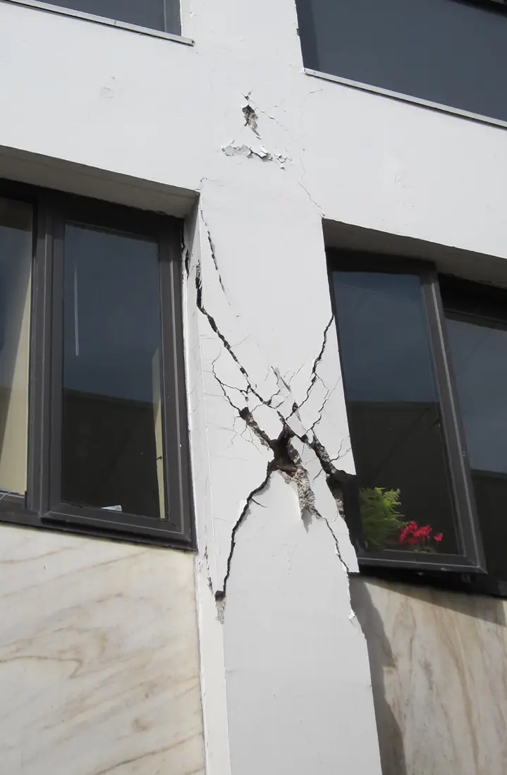
Avoid Bracing Frames with Infilled Walls
We need braced frames to carry the lateral load applied in an earthquake when there are not elements like shear walls in the building.
However, consideration of brick walls or infill walls is not a good option as it could damage the moment-resisting frame. Failure of the frame could lead to structural collapse.
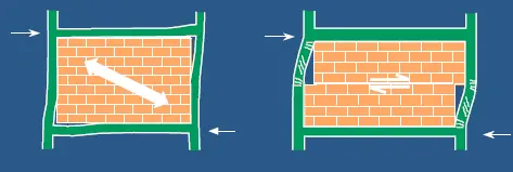
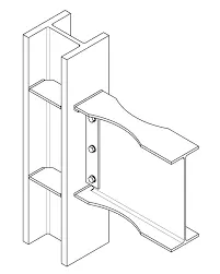
Therefore, proper construction details that allow the movement of the frame and that does not lead to failure of infill walls affecting the concrete frame, shall be used when designing.
A separation could be made between the concrete frame as shown in the following sketch.
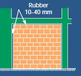
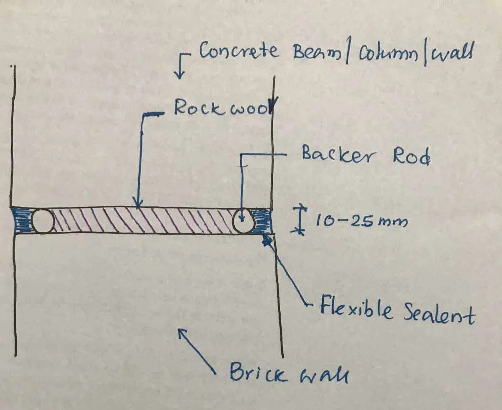
The filling between the brick and the concrete could be done in a different manner as required by the design. We may fill the gap with a material having the required fire rating. The following figure indicates a typical detail that can be adopted.
The use of polystyrene instead of Rockwool could not be accepted as we may not be able to meet the required fire resistance. However, in locations where there are no such requirements, we may use polystyrene.
Avoid Short Columns
The short column acts as a stiff element that may not fail in bending. However, there is a high possibility of short columns fail in shear.
By definition, the short column is relatively short in height when compared to its cross-section.
Even a slender column can become a short column when there are short brick walls on either side of the column.
Therefore, it is advisable to avoid partially infilled frames.
Avoid Hinge in Steel Column in Steel Structures [most important form seismic design principles]
Steel is a material that is subjected to local buckling failures mostly. Its failure is mainly due to the buckling of its components.
Further, steel is mostly utilized in the site capacity by racing the plastic limits. However, there is a reasonable margin for further deformations by yielding.
Apart from that, we prefer the failure of a beam that the failure of a column. Beam failure may localize but if a column is failed, the whole structure may collapse.
Therefore, we prefer the formation of the fingers in the beams earlier than columns. Therefore, having a rigid joint at the beam-column junctions could reduce the possibility of forming hinges in the beams.
Therefore, correct detailing practices shall be adopted when steel buildings are designed for earthquake loads.
Presently, when designing, we use the concept of a strong column and a weak beam.
It minimizes column failures and as a result, the structure is safe.
Reinforcement Detailing of Beams and Columns
Most of the failure of beam and columns occurs near the beam-column joint where there is high stress developed due to the cyclic loadings.
Special reinforcement detailing methods are adopted to maintain the confinement of the concrete.
The article seismic detailing of beams and columns could be referred to for more information on enforcement arrangements to be made on these elements.
Further, the article, performance based design could also useful to study to know more about the capacity-based design which considered in the seismic design too.
Apart from that we better have a good understanding of column failure methods when designing and detailing these types of structures.
Reinforcement Detailing of Beam-Column Joint
In addition to the failure close to the beam-column joint, failures within the joint have cause structural collapse. This was not included under the seismic design principles in the early days.
Early days, engineers did not aware much about it and did not pay more attention as does to the areas.
However, later it is realized that how the beam-column joint should be detailed.
The failure caused mainly due to the lack of confinement reinforcement within the joint.
We have to continue the shear links of the column even though the beam-column joint.
It is a bit of a challenging task with all the reinforcements of the beam and column. However, it is not impossible if planned properly.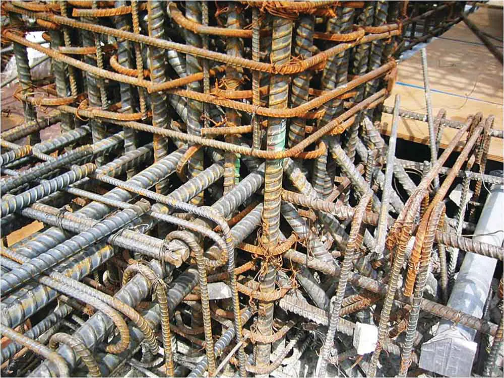
Even there is such congestion of reinforcements exists, they have placed the shear links of the column.
However, reinforcement detailing of this nature is not acceptable. This will create a weak joint that may even have internal honeycombs(cavities). There is no place for concrete to flow.
Therefore, attention shall be made to reinforcements especially when we dealing with a ductile structure. Improper detailing could lose the ductility of the structure.
Ductility of the Structures
Whether the building is steel or concrete ductility of the structure shall be maintained. This one of the most important factors to be considered out of other seismic design principles.
Rigid structures tend to fail in earthquakes as less dispassion of the energy from the seismic events. However, when the structure is ductile it absorbs the energy and it can withstand the forces applied from an earthquake.
A ductile structure can absorb the energy and undergoes deformation with the application of loads. The type of load applied to the structure will be cyclic and absorbing such energy by deforming the is also the ductility.
Further, ductility behavior allows the structure to under plastic deformations. The structure could reach limit states such as immediate occupancy, life safety, and collapse prevention based on the magnitude of the load. Depending on the occupancy category that planed the structure to behave, the design is done. This is called performance-based design.
The ductility of a structure can be increased by the following methods – Source – technical paper
- Increase compression reinforcements
- Increase concrete compressive strength
- Increase the ultimate concrete strain
The ductility of a structure can decrease for the following reasons.
- Increase tension reinforcements
- Increase steel yield strength
- Increase in axial load
The above factors directly affect the ductility of the structure these are basic seismic design principles to be incorporated in the structural desing.
Our expectation is the structure to deform absorbing the energy without brittle failure. Attention shall be made to the above factors when the designs are done.
Material Nonlinearity
When we design a concrete structure we consider it to behave in the linear range and the material properties in the nonlinear range are not taken into account.
However, in the seismic designs, we try to use the material strength as much as possible as per seismic design principles.
As discussed in the article performance-based design, there are occupancy levels that we can reach in the nonlinear range.
Let’s see what is the material nonlinearity by taking concrete as an example.
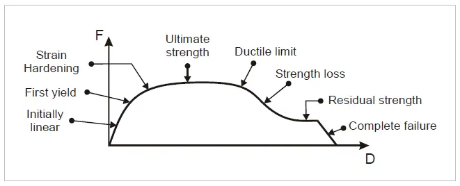
The above figure indicates material behavior and it reaching different zones such as linear range strain hardening, ultimate state, etc.
This behavior of the material is idealized during the analysis for simplicity. Further, this behavior of the material is represented by the hinge in the analysis. It represents the whole section that includes both the concrete and the reinforcements.
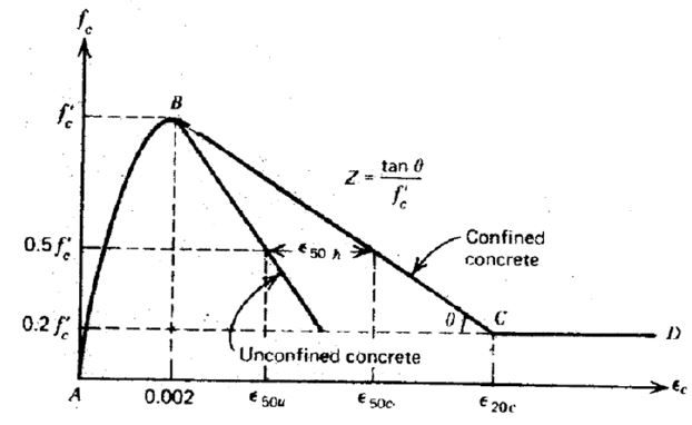
If we take concrete only, its behavior is repressed as the following curve. Variation of the stress and strain is indicated below.
The combination of concrete, steel, and the section properties is the hinge that represents the particular element behavior.
We get the status of the material by looking at the hinge behavior. The following curve indicates the force deformation of the hinge that represents the element.
Apart from that, it should be noted that we design structure to behave in the linear range for usual loads such as dead, wind loads, etc. Then the same structure is check for seismic loads. Based on the occupancy levels that the structure expected to behave, adjustments for the elements are made.
Use of Correct Peak Ground Acceleration (PGA)
Peak ground acceleration is the most important factor to be considered under seismic desing principles.
Further, the prediction of PGA is one of the most challenging takes in the earthquake engineering design.
In general, there are standards that specified the peak ground acceleration or acceleration coefficients that could be used for the desing.
In countries where there are no plate boundaries or when they are not close to a plate boundary, minimum values that could have specified in the relevant standard could be used.
In addition, attention shall be made to the return period which affects the magnitude of the PGA.
Lateral Load Resisting Systems for Earthquake Loads
The usual systems such as moment frames, shear walls, etc. could be used to resist the lateral loads applied on a structure.
The article lateral load resisting system could be referred to for further information.
There are other special techniques used to minimize the impact of the earthquake on the structure in seismic design principles.
There are call dampers. They absorb the entry of the oscillating building and as a result, the energy applied to the building will be dissipated.
The following types of dampers can be observed.
- Viscous dampers
- Viscoelastic dampers
- Friction dampers
- Vibration dampers (Tuned mass dampers)
- Yielding dampers
- Magnetic dampers