UBC 1997 seismic design example includes the calculation of the base shear and its distribution over a three-story building. Further, relevant areas to the design are also discussed in this article.
UBC 1997 seismic design process is discussed in another article on the web site. This article is a UBC 1997 seismic design example that elaborates the calculation process in actual conditions.
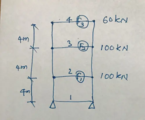
The figure below indicates the structural arrangement considered for UBC 1997 seismic design example.
This worked example is a static method of calculating the force to do the static analysis. The concept of this method is the lumped mass. We consider the mass of the structure is lumped at each floor level in this calculation.
Distribution of the forces due to the earthquake is done accordingly in following UBC 1997 seismic design example.
The following data were considered in this UBC 97 seismic design example.
- Zone factor: Seismic zone represent the peak ground acceleration that the structure is subjected to. In this example, I considered the building located in Zone 01 where the peak ground acceleration is 0.075g (g-gravitational acceleration). Therefore, Z = 0.075 – Table 16-I
- Soil Profile Type – SB – Rock – Appropriate category could be obtained from Table 16-J
- Cv = 0.08 – Table 16-R – based on zone factor and soil profile type
- Ca = 0.08 – Table 16-Q – based on the Zone factor and soil profile type
- Ct = 0.0731 – Reinforced concrete moment resisting frame – for this work example
- R = 3.5 – Table 16-N – Ordinary moment-resisting frame – for this working example
- I = 1 – Table 16-K – Occupancy category
- hn = 12m – Total height of the structure
Let’s calculate the period of the structure.
T = Ct(hn)3/4
T = Ct(hn)3/4 = 0.0731(12)3/4 = 0.471 s
Seismic weight of the structure
W = 100 + 100 + 60 = 260 kN
Generally, the seismic weight is the self-weight of the structure. However, depending on the type of the structure and as specified in UBC 97, the relevant components of the live load could be added to the dead weight.
Further, other permanent loads like super-imposed dead loads, machines on the floor, etc should be considered for the seismic dead weight.
Let’s calculate the base shear
V = ( CvI / RT ) W
V = ( 0.08 x 1 / 3.5 x 0.471 ) 260 = 12.618 kN
Check whether the base shear is within the limit.
Vmax = ( 2.5 Ca I / R ) W
Vmax = ( 2.5 x 0.08 x 1 / 3.5 ) 260 = 14.857 kN
Vmin = 0.11 Ca I W
Vmin = 0.11 x 0.08 x 1 x 260 = 2.288 kN
Hence,
Vmax < V < Vmin OK.
T = 0.471 s < 0.7 s
Therefore, no need to consider, Ft
Ft = 0
Ft – is the portion of base shear(V) considered concentrated at the top of the structure in addition to the forces distributed from base shear.
Further, Ft is taken not greater than 0.25 V where the T > 0.7 and it can be calculated from the following equation.
Ft = 0.07 T V
Force to be applied in the static analysis can be calculated from the following equation.

In this UBC 1997 seismic design example, Ft = 0.
Forces to be applied at each floor level can be calculated as follows.
F1 = 12.618 x 100 x 4 / [100 x 4 + 100 x 8 + 60 x 12] = 12.618 x 400 / 1920 = 2.629 kN
F2 = 12.618 x 100 x 8 / [100 x 4 + 100 x 8 + 60 x 12] = 12.618 x 800 / 1920 = 5.258 kN
F3 = 12.618 x 60 x 12 / [100 x 4 + 100 x 8 + 60 x 12] = 12.618 x 720 / 1920 = 4.732 kN
These forces could be applied to the computer model, and bending, shear, deflection could be obtained from the same to proceed with the desing.
Further, limiting values of the drift, etc shall be checked as per the code requirement as discussed in the article UBC 1997 seismic design.
In addition, for more information on seismic designs, the Wikipedia article earthquake engineering could be studied.