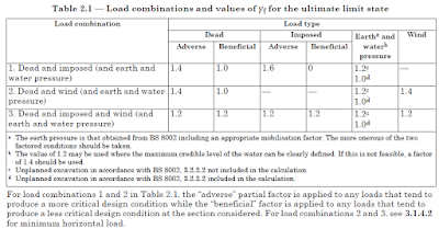
Factors for load combinations BS 8110
Depending on the effect of loading on the structure we select the safety factors for load combinations. The following table in BS 8110 shows the load factors for load combinations.
For example, we can create load combinations as follows.
Ultimate load combination
1.4 Dead Load + 1.6 Live Load
Service Load Combination
1.0 Dead Load + 1.0 Live Load
When earth pressure and dead load is considered, we create following load combination
1.4 Dead Load + 1.2 Earth Pressure
This combination also can be used when water pressure is applied or both the water and earth pressure is applied.
When we need to find the highest effect on the structure due to the above loading we also modify the above load combination as follows depending on the structural engineer’s consent.
1.0 Dead Load + 1.2 Earth Load
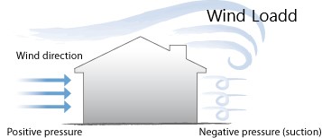
Situations where the dead loads tend to reduce the forces (Bending Moments, shear forces, etc) we use this combination to get the maximum effects on the structure. A similar action on loads is considered for the wind load as well.
1.4 Dead Load + 1.4 Wind Load
1.0 Dead Load + 1.4 Wind Load
For some structural elements, load combinations with the factor of 1.4 (for dead load) give higher forces while other elements show higher forces with a factor of 1.0. Hence, it is advisable to consider both the combinations when analyzing a structure. In addition, it is observed that some engineers use a factor of 0.9 (for dead load) to be on the safer side especially when they are analyzing tall structures.
when dead, live and wind or earth pressure is applied on a structure, following load combinations can be created.
1.2 Dead Load + 1.2 Live Load + 1.2 Wind Load
After we create all the load combinations as required by the analysis, the envelope is created to find the overall effect of the load combinations. If we design structural elements with the envelope we need to be very careful with the analysis outputs.
For example, consider the design of a slab.
Some software, when asked to show results of the envelope they show maximum values or minimum vales depending on default settings of the software, without considering the sign conversions. It might show maximum values. It may disregard the maximum negative value(absolute value) and may show the smaller negative value as we consider the maximum values on the positive side.
Therefore is very important to get the absolute maximum values or get the values of each load combination for the design.
In addition, we need to be very careful when analyzing columns with load combinations as the axial forces and bending moments in both directions affect the design.
For example consider column with higher axial load and small bending moments, for this column we can find certain reinforcements. Consider another column with small axial load and higher bending moments, it may give a higher amount of reinforcements than that of the above column. If we consider the results of the envelope and do the design, we take the maximum axial load and maximum moments for the design. The amount of reinforcement found in the analysis may be most probably higher than the above two methods, and we will then provide a higher amount of reinforcements than the required amount of reinforcements. Therefore we need to be very careful when working with load combinations and the envelope.
This table is also used for the analysis of alternative loading effects on the structure. We can create load combinations BS 8110 in a way that take the effects of alternative actions. For example, we can assign different load cases to an adjacent span. Then we can adjust the factor in a way that the alternative effect is considered.