Axially loaded bolt connection design is discussed in detail with a worked example and while discussing the technical background related to the design.
In this article, we are concentrating on the design of steel plates with regular bolt arrangements having applied the axial tension.
Firstly, let’s discuss the desing procedure of the steel plate having the bolts.
Desing Procedure
The following step can be followed during the desing.
- Evaluate the material properties
Initially, you select a plate thickness to proceed with the design. Based on the plate thickness and the steel grade the yield strength (fy) and ultimate strength (fu) can be obtained from Table 3.1 of Eurocode 3.
Then obtain the γm0 and γm2 from Clause 6.1. These values may change as per the national annexures.
- Calculate the cross-section of the plate or the area that applies the axial tension.
Different arrangement of the bolts needs to be considered and we have to find the critical cross-section having the smaller area which leads to increase the stress.
The plate is check for its gross cross-section and critical section (after reducing the hole area). The minimum of the following capacities is taken as plate capacity (Nt,Rd).
-
-
- Npl,Rd = Afy / γm0 Plate capacity of gross cross section (Plastic Resistance). Here, A – gross crosection
- Nu,Rd = 0.9Anetfy /γm2 Plate capacity for gross section (Ultimate Resistance). Here, Anet – net cross section
-
- Check the plate capacity found above is less than the applied load.
Plate Capacity = (Nt,Rd) = min[Npl,Rd , Nu,Rd ]
Applied Load = NEd
NEd/Nt,Rd < 1
Worked Example: Bolt Connection Design; Axially Loaded Plate
Design Data
- Applied load on plate 300kN
- Thickness of the plate 12mm
- Width of the plate 180mm
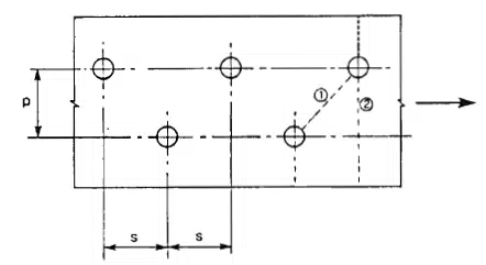
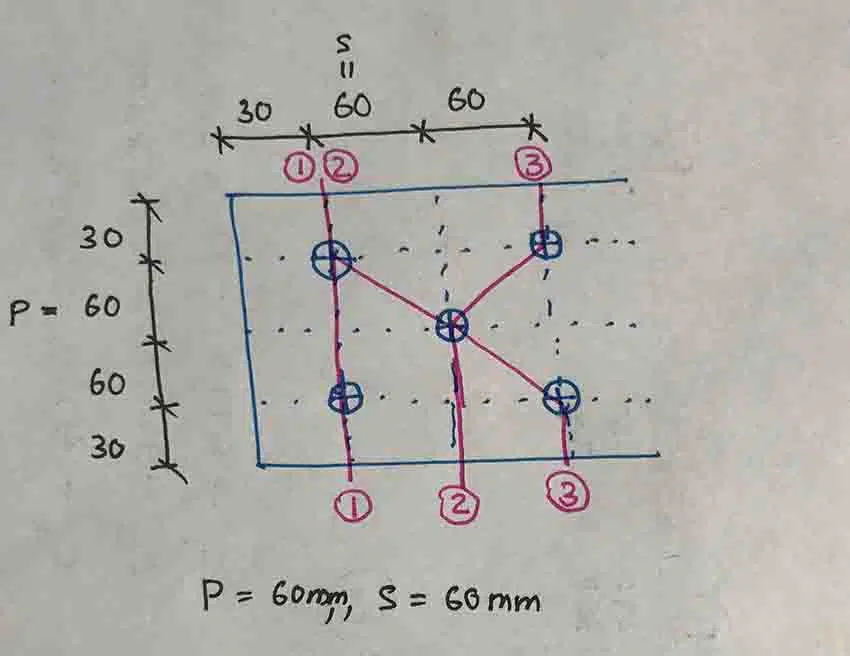
- Bolt spacings; s = p = 60mm (refer above figure for s & p)
- Bolt Diameter 16mm
- Steel Grade S275
Steel grade S275 and plate thickness 10mm < 40mm, the following design parameter can be obtained from Table 3.1 of EN 1993-1-1 (EC3).
fy = 275 N/mm2
fu =430 N/mm2
From clause 6.1, obtained the partial factors.
γm0 = 1.0
γm2 = 1.25
Cross sectional area of the plate
A = 180 x 10 = 1800 mm2
Plastic Resistance Npl,Rd = Afy / γm0
Npl,Rd = 1800 x 275 / 1.0 = 495000 N = 495 kN
Calculate the Capacity of Plate with reduction of Holes Area
The method of calculating the deduction of bolt hole area is given in Cl 6.2.2.2.
It is quite easy to calculate the deduction as there is an equation for that.
Deduction = t [ nd0 – Σ (s2/4p) ]
Cross section 1 – 1
Deduction = 10 [ 2 x 18 – 0 ] = 360 mm2
Cross section 2-2
Deduction = 10 [ 2 x 18 – (602/4×60) ] = 210 mm2
Cross section 3-3
Deduction = 10 [ 2 x 18 – {(602/4×60) + (602/4×60)} ] = 240 mm2
The maximum deduction was in part 1-1
Therefore,
Anet = 1800 – 360 = 1440 mm2
Calculate ultimate resistance, Nu,Rd
Nu,Rd = 0.9 x 1440 x 430 / 1.25 = 445824 N = 445.8 kN
Plate Capacity = (Nt,Rd) = min[Npl,Rd , Nu,Rd ]
Nt,Rd = min[495 , 445.8 ] = 445.8 kN
NEd/Nt,Rd < 1
300/ 445.8 < 1 Plate can carry the applied load.
Further, reading on steel beam design the article Steel Beam Desing Worked Example may be reffered.