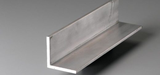
Single Angle Section Design Worked Example
Single angle section design using EN 1993-1-1 is discussed in this article by a worked example. Angle section subject to compressive force is designed with referring relevant section in the code.
The design procedure of the compression members is the same as discussed in the article Steel Column Design using Eurocode 3.
Let’s discuss the design with a worked example.
Desing Data
- Angle section 60x60x6
- Lenght of the angle section 600mm
- Applied Load 100kN
- Single raw of bolts
- Steel grade S275
Classification of the Sections
Let’s find the material data
Thickness of section = 6 mm ≤ 40 mm and
Steel grade S275
From Table 3.1 of EN 1993-1-1,
fy = 275 N/mm2
From Table 5.2 (sheet 3 of 3)
ε = √(235/fy) = √(235/275) = 0.924
From Table 5.2 (sheet 3 of 3)
h/t = 60 / 6 = 10 ≤ 15ε = 15 x 0.924 = 13.86
(b+h) / 2t = (60+60) / (2×6) = 10 ≤ 11.5ε = 11.5 x 0.924 = 10.626
Therefore, section is class 3
Compression Capacity of Cross Section
NEd / Nc,Rd ≤ 1.0
Nc,Rd = Afy / γM0
γM0 = 1.0 from Clause 6.1
A = 695 mm2
Nc,Rd = Afy / γM0 = 695 x 275 / 1.0 = 191.1 kN
NEd / Nc,Rd = 100 / 191.1 = 0.524 < 1
Section satisfy the compression capacity.
Buckling Resistance
NEd / Nb,Rd ≤ 1.0
Calculate the buckling length, Lcr
We need to check the buckling resistance in the critical axis. Therefore, we consider axis Y-Y, Z-Z, and V-V and find the critical reduction factor(less the value higher the reduction in the bending moment. This is a must in angle section design.
Find the buckling length in each axis. Buckling length may be considered as specified in the BS 5950.
Y-Y axis; 0.85 x 600 = 510 mm
Z-Z axis; 1.0 x 600 = 600 mm
V-V axis; 0.85 x 600 = 510 mm
From section property data, obtain the radius of gyration (i)
i – Y-Y axis = 18.3 mm
i – Z-Z axis = 18.3 mm
i- V-V axis = 11.8 mm
λ1 = 93.9ε = 93.9 x 0.924 = 86.4
λ‾ = (Lcr / i)( 1 / λ1)
Note: the symbol λ¯ shall be as indicated in the code. There is a slight difference in the symbol when compared with the code.
Calculate for each direction to obtain the critical factor.
λ‾ Y-Y axis = (510 / 18.5)( 1 / 86.4) = 0.323
λ‾ Z-Z axis = (600 / 18.5)( 1 / 86.4) = 0.379
λ‾ V-V axis = (510 / 11.8)( 1 / 86.4) = 0.5
When the single angle section design the connection is made by a single bolt, λ¯eff shall be considered. If there are two or more bolts, eccentricities may neglect.
In this example, consider the angle connected through one leg. Therefore, consider, λ¯eff
Y-Y axis; λ¯eff = 0.5 + 0.7λ‾ = 0.5 + 0.7×0.323 = 0.726
Z-Z axis; λ¯eff = 0.5 + 0.7λ‾ = 0.5 + 0.7×0.379 = 0.765
V-V axis; λ¯eff = 0.35 + 0.7λ‾ = 0.35 0.7×0.5 = 0.7
The critical reduction factor is the less value of “χ”. This value become lesser when Ø is larger. This value becomes larager when is λ¯eff higher. Therefore, we select
λ¯eff = 0.765
Now obtain Buckling curve from Table 6.2 of EN 1993-1-1.
For angle sections, the buckling curve is ” b “.
Obtain α from Table 6.1 of EN 1993-1-1.
α = 0.34
Now calculate Ø from Cl. 6.3.1.2
Ø = 0.5[ 1 + 0.34(λ¯0.2 ) + λ¯2] = 0.5 [ 1 + 0.34 (0.765 – 0.2) + 0.7652] = 0.889
Calcualte reduction factor, χ
χ = 1 / [ Ø + √(Ø2 – λ¯2) ] = 1 / [ 0.889 + √( 0.8892 + 0.7652)] = 0.742
Now calculate the buckling resitance
Nb,Rd = χAfy / γM1
Nb,Rd = 0.742 x 695 x 275 / 1.0 = 141.8 kN
NEd / Nb,Rd < 1.0
NEd / Nb,Rd = 100 / 141.8 = 0.7 < 1
Section is adequate.
Further reading on structural steel, you may refer to the article Wikipedia article.


