Steel Column Design using Eurocode 3
Steel column design for Eurocode 3, EN 1993-1-1, is discussed in this article. Each design and design process is discussed comprehensively.
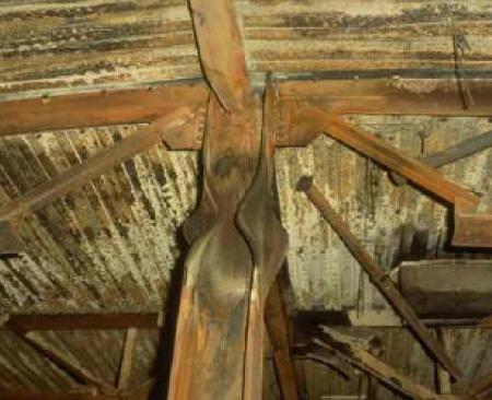
Steel column is designed for axial compression and the bending stress induced by the connecting elements. Not like the concrete steel is weak in compression. Mainly, there are two types of failures in steel columns.
- Crushing of Material – Failure in the material
- Member bucking (Overall buckling or local buckling)
Crushing Materials
Reaching the material to its capacity and failing due to inadequate capacity to carry the applied load.
This kind of failure could be due to the inadequate compressive strength and or cross-sectional area.
Member Buckling
Overall bucking or local bucking could lead to steel column design failures. Local bucking is dependent on the sectional properties.
Overall buckling depends on several factors.
- Length of the column
- Restrains at each end (unrestrained, partially restrained, and fully restrained)
- Sectional properties ( cross-sectional area, shape, etc.)
You may refer to the article on column failure methods for different types of concrete column failures.
Let’s discuss the desing aspect of the axial load Column.
Steel Column Design Procedure
- Classification of Section
Firstly it is required to classify the section according to the dimensions of the section and material properties.
Based on the slenderness limits, classification of section into categories, Class 1, Class 2, Class 3, and Class 4. Accordingly, Class 1,2 & 3 sections are classified into non-slender sections and Class 4 sections are classified as slender sections.
You may refer to Cl 5.5.2 of EN 1993-1-1 (EC3) for further information.
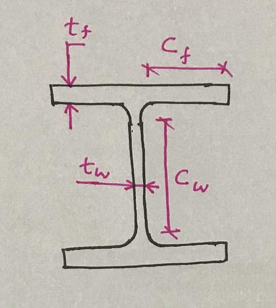
Consider H section, let see what are the limits available to classify the section. The limits are as follows as indicated in Table 5.2.
| Ratio | Class 01 | Class 02 | Class 03 | |
| Compression Flange of Rolled Section | Cf/tf | 9ε | 10ε | 14ε |
| Web of Rolled Section | Cw/tw | 33ε | 38ε | 42ε |
Where, ε = √(235/fy)
- Plastic Resistance or Resistance of Cross Section, Nc, Rd
- Non-Slender Sections: Class 1, 2 and 3
Nc,Rd = Afy / γm0
- Slender Section: Class 4
Nc,Rd = Aefffy / γm0
A and Aeff shall be as per the Cl 6.2.2.1 and Cl 6.2.2.5 respectively.
After calculating the resistance, the following capacity check shall be done.
NEd / Nc,Rd ≤ 1.0
- Buckling resistance, Nb,Rd
Firstly, calculate the buckling resistance depending on the class of the section.
- Non Slender Section [ Class 1,2 or 3]
Nb,Rd = χ A fy / γm1
- Slender Section [Class 4]
Nb,Rd = χ Aeff fy / γm1
When A and Aeff are determined hole for fasteners at the column ends need not to be taken into account.
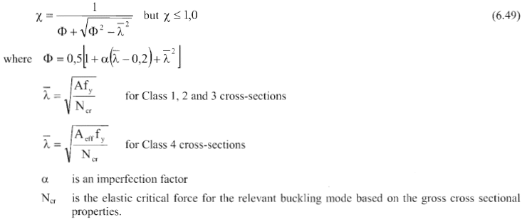
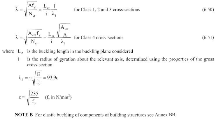
Here, “χ” is a reduction buckling of the section. It can be calculated from the following equation.
α is an imperfection factor to be obtained from Table 6.1 of code indicated below.
| Buckling Curve | a0 | a | b | c | D |
| Imperfection factor α | 0.13 | 0.21 | 0.34 | 0.49 | 0.76 |
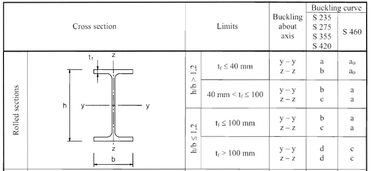
Here a0, a, b, c and d are buckling curves shall be selected from Table 6.2: Selection buckling curve for cross-section given in EN 1993-1-1. The part of Table 6.2 that indicates the curves for the Rolled sections indicate in the following figure.
A simplified method is given in Cl 6.3.1.3 of EN 1993-1-1 can be used to calculate the λ‾.
- Check NEd / Nb,Rd < 1
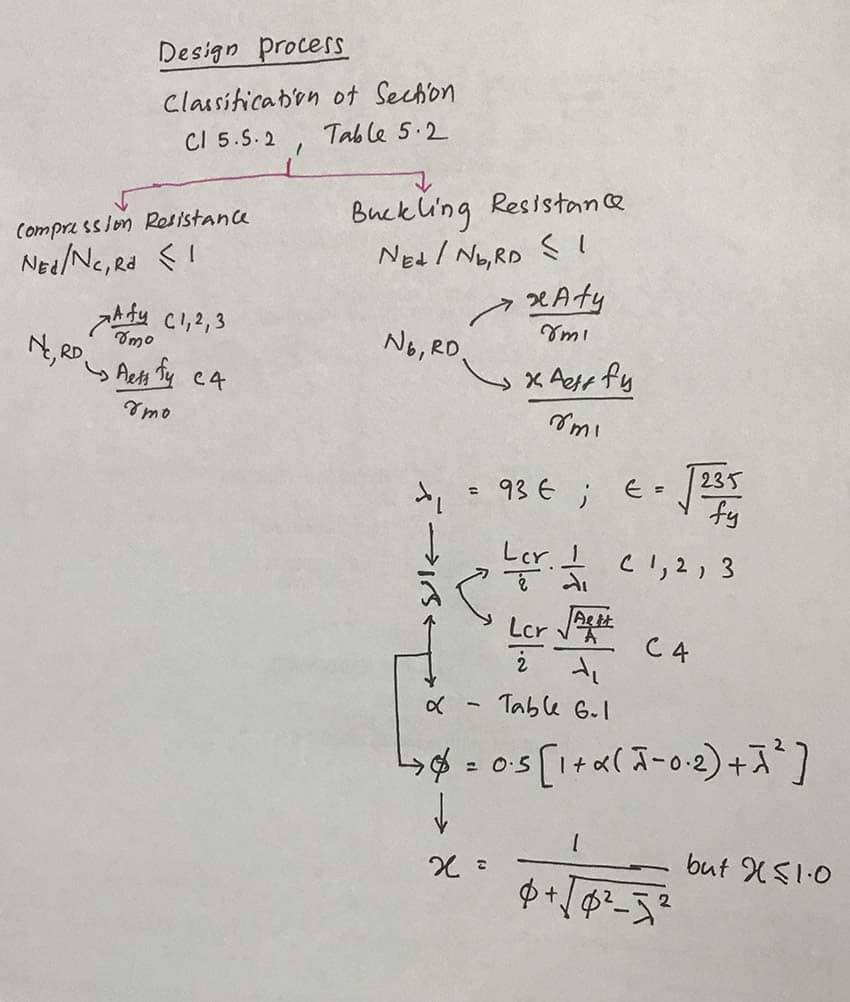
The design process flow chart can be illustrated as follows.
You may refer to the other article published under EC3 for worked example for further clarification on the calculation process.

