The steel beam design worked example elaborates the design of a simply supported beam having a uniformly distributed load. The beam is considered as simply supported and the design data for calculating the bending moment and shear forces are given below.
Further, the section properties to be considered are also given in each stage fo checking the section.
Theoretical aspects and code design procedures are discussed in the article design of the steel beam as per BS 5950.
Design Data
- Load UDL 20 kN/m
- Span of the beam 6m
- Beam is simply supported
- Desing strength of steel, Py = 275 N/mm2
Maximum Bending Moment
= wl2/8 = 20 x 62 / 8 = 90 kNm
Maximum shear force
= wl/2 = 20 x 6 / 2 = 60 kN
Consider universal beam 500x200x89.7 kg/m (Py = 275 N/mm2 )
Section Data
- D = 500 mm
- T = 16 mm
- t = 10 mm
- B = 200 mm
- b = 100 mm
- r1 = 20 mm
- d = 500 – 16 x 2 – 2 x 20 = 428 mm
- Sx = 2175×103 mm3
- Zx = 1914×103 mm3
- ry = 43.3 mm
Let’s start the steel beam design calculation. Under this steel beam design calculation, the following checks are done.
- Section Classification
- Shear Design
- Design for bending
- Check for lateral torsional buckling
- Deflection check
- Web bearing check
- Web buckling check
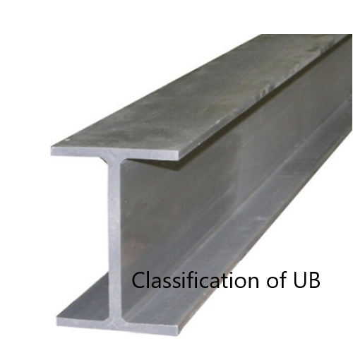
Classification of Section
The first step of the steel beam design is the classification of the section to know whether it is plastic, semi-plastic, compact, slender.
T = 16 mm, Py = 275 N/mm2
ε = (275/Py)0.5 = 1
Check Flange
b/T = 100 / 16 = 6.25 < 9ε = 9 – Flange is Plastic
Check Web
d/t = 428 / 10 = 42.8 < 80ε = 80 – Web is Plastic
Further, d/t < 70ε = 70 – Therefore, no need to check for shear buckling
Therefore, section is Plastic
Design for Shear
Design shear force, Fv = 60 kN
Pv = 0.6 Py Av = 0.6 Py tD = 0.6 x 275 x 10 x 500 x 10-3 = 825 kN
Fv < Pv Shear capacity is OK
Depending on the shear force, it is decided whether section is subjected to low or high shear in steel beam design.
Design for Bending
Check whether section is subjected to low shear or high shear
60% x Pv = 0.6 x 825 = 495 kN
Fv < 0.6 Pv Section subjected to low shear
Mc should be less than 1.2PyZx or Py Sx as per Cl. 4.2.5.1 and Cl. 4.2.5.2
Mc ≤ 1.2PyZx = 1.2 x 275 x 1914 x103 x 10-6 = 613.62 kNm
Mc = Py Sx = 275 x 2175 x 103 x 10-6 = 598.125 kNm
Therefore,
Mc = 598.125 kNm > 90 kNm
Bending ok
Check Lateral Torsional Buckling
Mx < Mb / mLT
In this example, no intermediate restrains were considered
mLT = 0.925, Table 18, BS 5950
Mb = Pb Sx Cl. 4.3.6.4
There are two methods to check lateral-torsional buckling as discussed in the article steel beam design as per BS 5950. They are the rigorous method and the simplified method.
In this steel beam design example, we discussed both the methods to elaborate on the procedures that need to be followed using either method.
Further, the main difference between these two methods is evaluating bending strength.
Rigorous Method
Mb = Pb Sx
Pb is depending on the λLT and Py
λLT = uvλ√(βw)
λ = LE / ry
LE – to be taken from Table 13 as per the Cl. 4.3.5.1 and consider LLT = L – span
LE = 1.0 LLT = 1 x 6 = 6 m
λ = LE / ry = 6000 / 43.3 = 138.568
For rolled I and H sections, Cl. 4.3.6.8
x = D / T used with u = 0.9
x = D / T = 500 / 10 = 50
βw to be obtained from Cl 4.3.6.9
βw = 1 for Class 1 plastic or Class 2 Compact sections
v – slenderness factor to be obtained from Table 19 based on the λ / x and η
λ / x = 138.568 / 50 = 2.771
η = 0.5 for equal flanges
v = 0.919 from Table 19
λLT = uvλ√(βw) = 0.9 x 0.919 x 138.568 x √(1) = 114.6
λLO can be obtained from Table 16 (refer bottom of the table)
If λLO ≥ λLT ; Pb = Py or Othewise Pb shall be taken from Table 16 for rolled sections.
If λLO ≥ λLT no allowance needs to be made for lateral-torsional buckling and otherwise check for lateral-torsional buckling.
Py = 275 N/mm2 ; λLO = 37.3
λLO < λLT Therefore check for lateral torsional buckling
From Table 16, for λLT = 114.6 ; Pb = 102 N/mm2
Mb = Pb Sx = 102 x 2175 x 103 x 10-6 = 221.85 kNm
Mb / mLT = 221.85 / 0.925 = 239.838 kNm
Therefore, Mx = 90 kNm < Mb / mLT = 239.838 kNm
Section is adquate.
Simplified Method
Note: Both methods need not be done when designing a beam. Following either the simplified method or rigorous method is adequate.
Mb = Pb Sx : Cl. 4.3.7
In this method, the determination of the Pb is different when compared with the previous method. This method provides conservative answeres. Pb can be obtained from Table 20 of BS 5950 based on √(βw) (LE / ry ) and D / T
βw = 1 ; previous calculation
LE / ry = 138.568 ; previous calculation
√(βw) (LE / ry ) = 10.5 x 135.568 = 138.568
D / T = 500 / 16 = 31.25
Pb = 116.646 N/mm2 From Table 20
Mb = Pb Sx = 116.646 x 2175 x 103 x 10-6 = 253.705 kNm
Mb / mLT = 253.705 / 0.925 = 274.3 kNm
Therefore, Mx = 90 kNm < Mb / mLT = 274.3 kNm
Section is adequate
Defelection
Maximum defelection ( δ ) for simply supported beam having uniformly distributed can be evaluated from following equation.
δ = 5WeL4 / (384EI)
This equation can be further simplifed as follows.
δ = 0.104MmaxL2 / (EI)
Since we evaluate the deflection due to the imposed loads, consider imposed load as 10 kN/m in this calculation.
δ = 0.104 x 90 x 106 60002 / (205 x 103 x 478 x 106 ) = 1.7 mm
Assuming brittle finishes to be used
Span / 360 = 6000 / 360 = 16.7 mm
δ < Span / 360, Hence deflection is Ok
Different methods of calculating the defelections are discussed in the Wikipedia article deflection (engineering).
Web Bearing Capacity
It is a must to check the capacity of the web in steel beam design. Web bearing and buckling is done in this catogory.
Pbw = (b1 + nk) tPyw

t = 10 mm
T = 10 mm
r = 10 mm
g = 5 mm
be = 5 mm
b1 = t + T + 0.8r – g = 10 + 10 + 0.8 x 10 – 5 = 23 mm
k = T + r = 16 + 20 = 36 mm (for rolled section)
at end,
n = (2 + 0.6be/k) but ≤ 5
n = (2 + 0.6 x 5 / 36) = 2.083 < 5 Pyw = 275 N/mm2 from Table 9
Pbw = (b1 + nk) tPyw = (23 +2.083 x 36 ) x 10 x 275 x 10-3 = 269.5 kN
Support reation is 60 kN.
Web bearing is Ok and no stiffeners are required.
When Fx > Pbw , we need to provide stiffeners to cater to balance force ( Fx – Pbw ). The capacity of the stiffeners shall be obtained from Ps = As.net Py. Where As.net is the cross-sectional area of the stiffness. If the web and stiffness have different strengths, the smaller value should be used to calculate both Ps and Pbw.
Web Buckling
When ae ≥ 0.7d
Px = 25εt Pbw /√[ ( b1 + nk ) d ]
When ae < 0.7d
Px = [ (ae +0.7d)/1.4d] {25εt Pbw /√[ ( b1 + nk ) d ] }
Where
ae = 0.7d = 23 / 2 = 11.5 mm < 0.7 x 428 = 300 mm
Px = [ (ae +0.7d)/1.4d] {25εt Pbw /√[ ( b1 + nk ) d ] }
Px = [ (11.5 +0.7×428)/1.4×428] {25x1x10x275 /√[ ( 23 + 2.083×36 ) 428 ] } = 174.3 kN
Fx < Px
No stiffeners are required.
Beam satisfies all the checks.