The lateral torsional buckling is the deformation of the beam due to the applied loads away from its longitudinal axis. Further, it causes steel beams failures.
The deformation could occur as translational and rotational movement of the section, and these types of movements are identified as lateral torsional buckling. Figure 1 indicates the deformations that can be seen as a result of lateral torsional buckling.
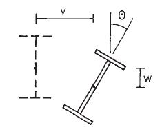
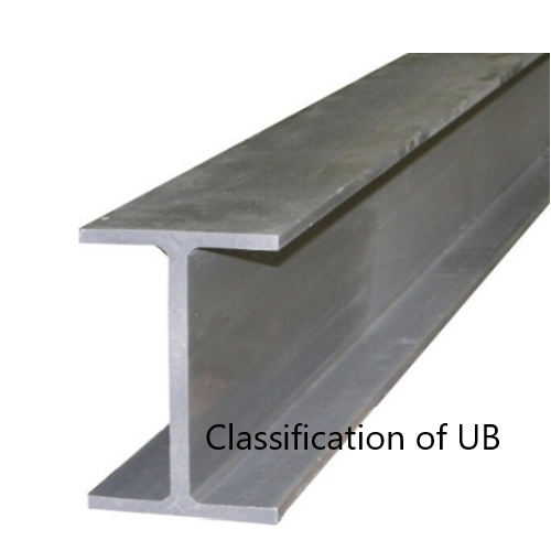
Figure 01 Lateral Torsional Buckling
As indicated in Figure 01, the beam can be decoded with the application of loads. This deformation could occur laterally and vertically with a rotation of the member. In the design of steel beams, lateral restains are provided in spacings calculated to avoid failures.
Lateral torsional buckling occurs with the increase of loads based on section properties and its restrains. Loading on a beam can not be avoided as it is the purpose of having the beam.
However, the section properties and the restrain conditions can be controlled during construction and design.
- As discussed above too, lateral-torsional buckling occurs when the beam is not full restraints in the lateral direction along the compression flange of the beam.
- The beam is considered full restraint laterally when the connection between the beam and the floor can resist at least a lateral force of 2.5% of the maximum force in the compression flange of the beam.
When there are no restraints, it is required to provide sections having higher section modulus, if the restraints are provided properly, the size of the beam can be reduced.
It is a proven fact that failures cause the moment of the section away from its axis. Therefore, providing the restrains will definitely reduce the section dimensions.
However, based on the structural arrangement of the structure, there may not be able to provide the lateral restrains at ends or internally. In such situations, beams need to be designed without considering the lateral restrains.
Mainly, the failures to restrain the compression flange cause the lateral movement of the section. Therefore, lateral-torsional buckling can be avoided by providing internal restains.
Intermediate restraints are provided to reduce the unsupported length in the lateral direction. They should be capable of resisting lateral forces and should have the capacity to retain without deforming. The axial capacity of intermediate restrains shall be checked as per the guidelines in the BS 5950.
Design for Lateral Torsional Buckling of Beam
Section to satisfy the bending requirements, it shall have the bending capacity in the direction of bending (Mc) grater than the applied bending moment and lateral torsional buckling capacity greater the moment generated due to the buckling.
Mx < Mb/mLT and Mx ≤ Mc
In this article, the procedure needs to be followed in calculating the lateral-torsional buckling capacity is discussed. And the article steel beam design to bs 5950 could be referred bending capacity checks.
Lateral Torsional Buckling resistance ( Mb/mLT ) can be calculated as illustrated below. Two methods used to evaluate the Buckling Resisting Moment ( Mb ). Based on the preference of the designer, either method could be used.
- Rigorous method
- Simplified method
| Rigorous Method | Simplified Method | |
| Class 1 – Plastic Class 2 – Compact |
Mb = PbSx | Mb = PbSx |
| Class 3 – Semi-Compact | Mb = PbZx or Mb = PbSx,eff |
Mb = PbZx |
| Class 4 – Slender | Mb = PbZx,eff | |
| Pb based on λLT and Py | Pb based on √( βw) LE/ry and D/T ratio | |
| λLT = uvλ √( βw) |
When both methods are compared, it seems that the main difference is the method of evaluating the Bending Strength ( Pb ).
A detailed explanation of the method of designing as a steel beam is discussed in the article steel beam design worked example.
Check Lateral Torsional Buckling
Lateral torsional buckling Example
Data:
- Consider simply supported beam with not intermediate restraints
- Beam span 6m
- Maximum design bending moment 100 kNm
As discussed above there are two methods for checking the lateral-torsional buckling. Let’s discussed them with a worked example.
It is required to satisfy the following equation for a section to be ok for buckling.
Mx < Mb / mLT
For simplicity, In this example, no intermediate restraints are considered.
Then,
mLT = 0.925, Table 18, BS 5950
Mb = Pb Sx Cl. 4.3.6.4
Firstly let’s check the buckling capacity with rigorous method.
The following section data are considered in the calculation
- D = 500 mm
- T = 16 mm
- t = 10 mm
- B = 200 mm
- b = 100 mm
- r1 = 20 mm
- d = 500 – 16 x 2 – 2 x 20 = 428 mm
- Sx = 2175×103 mm3
- Zx = 1914×103 mm3
- ry = 43.3 mm
- Section is plastic as per its dimensions
Rigorous Method
Mb = Pb Sx
Pb is fuction of λLT and Py
λLT = uvλ√(βw)
λ = LE / ry
LE – can be found from Table 13 (Cl. 4.3.5.1) and consider LLT = L – span
Thus,
LE = 1.0 LLT = 1 x 6 = 6 m
λ = LE / ry = 6000 / 43.3 = 138.568
For rolled I and H sections, Cl. 4.3.6.8
x = D / T used with u = 0.9
x = D / T = 500 / 16 = 31.25
βw can be be obtained from the Cl 4.3.6.9
βw = 1 for Class 1 plastic or Class 2 Compact sections
v – slenderness factor – obtained from Table 19 as per the λ / x and η
λ / x = 138.568 / 31.25 = 4.434
For equal flanges η = 0.5
v = 0.84 from Table 19 [conservative value taken; λ / x = 4.5, interpolation shall be used for exact value]
λLT = uvλ√(βw) = 0.9 x 0.84 x 138.568 x √(1) = 104.8
λLO to be obtained from Table 16 (indicated at the bottom of the Table 16)
If λLO ≥ λLT ; Pb = Py or Othewise Pb shall be taken from Table 16 for rolled sections.
If λLO ≥ λLT no allowance needs to be made for lateral-torsional buckling and otherwise check for lateral-torsional buckling.
Py = 275 N/mm2 ; λLO = 34.3
λLO < λLT
Hence, check for lateral torsional buckling
From Table 16, for λLT = 104.8 ; Pb = 117 N/mm2
Mb = Pb Sx = 117 x 2175 x 103 x 10-6 = 254.5 kNm
Mb / mLT = 254.8 / 0.925 = 275.4 kNm
Therefore, Mx = 100 kNm < Mb / mLT = 239.838 kNm
Section is adquate for lateral torsional buckling as per the rigorous method.
Simplified Method
We need not doing both the calculation to check the buckling resistance.
Mb = Pb Sx : Cl. 4.3.7
The determination of the Pb is not the same as the rigorous method.
This method provides conservative answeres.
Pb can be obtained from Table 20 of BS 5950 as per √(βw) (LE / ry ) and D / T
βw = 1 ; as previous calculation.
LE / ry = 138.568 ; from above calculations
√(βw) (LE / ry ) = 10.5 x 135.568 = 138.568
D / T = 500 / 16 = 31.25
Now, can obtain from Tabe 20
Pb = 116.646 N/mm2
Mb = Pb Sx = 116.646 x 2175 x 103 x 10-6 = 253.705 kNm
Mb / mLT = 253.705 / 0.925 = 274.3 kNm
Thus, Mx = 100 kNm < Mb / mLT = 274.3 kNm
Therfore, the section is adequate.