An overview of the procedures that need to be followed in steel beam design is discussed in this article. There are basic steps to be followed to complete the design. These steps can be categorized into six main subjects according to the BS 5950.
The following steps in the following order could be followed to do the design correctly.
- Section Classification
- Shear Capacity
- Bending Capacity
- Lateral Torsional Buckling
- Deflection
- Web Bearing
- Web Buckling
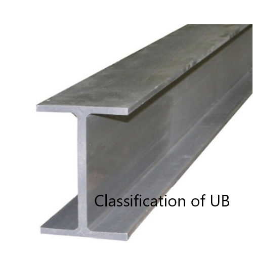
Classification of Section
Classification is done based on the aspect ratios of the section.
Based on the b/t and d/t flange and web are classified under the categories Plastic, Compact, Semi-Compact, and Slender sections. Click here for more on the Classification of sections.
Further, the first step of the steel beam design is the classification of the section. No design shall be carried out without classifying the beam.
Shear Capacity
Pv = 0.6PyAv
Pv > Fv
Where
Pv – Design shear strength
Fv – Design Shear Force
Av is the shear area and it shall be calculated as stipulated in the BS 5950. For rolled I and H sections and channel sections, load parallel to the web
Av = tD
Bending Capacity
The bending capacity equation in steel beam design is selected based on the shear force in the section.
There are different sets of equations for Low Shear ( Fv ≤ 0.6Pv ) and High Shear ( Fv ≥ 0.6Pv ).
Further, for avoiding irreversible deformation under service loads, the value of Mc should be limited to 1.5PyZ generally and to 1.2PyZ in the case of the simply supported beam or cantilever.
Low Shear ( Fv ≤ 0.6Pv )
| Section Classification | Moment Capacity |
| Class 1 – Plastic Class 2 – Compact |
Mc = PyS |
| Class 3 – Semi-Compact | Mc = Py Z or Mc = PySeff |
| Class 4 – Slender | Mc = PyZeff |
Where,
S – Plastic Section Modulus
Seff – Effective Plastic Modulus
Z – Section Modulus – Elastic
Zeff – Effective Elastic Section Modulus
High Shear ( Fv ≥ 0.6Pv )
| Section Classification | Moment Capacity |
| Class 1 – Plastic Class 2 – Compact |
Mc = Py(S – ρSv) |
| Class 3 – Semi-Compact | Mc = Py(Z – ρSv/1.5) or Mc = Py( Seff – ρSv) |
| Class 4 – Slender | Mc = Py( Zeff – ρSv/1.5) |
Based on the classification of the section and after check the low shear and high shear conditions, bending capacity can be evaluated.
For more information on other checks to be done can be referred by clicking the relevant item from the above list of checks.
Lateral Torsional Buckling
Beam shall be checked for the lateral torsional buckling base on its span and as per the arrangement of the internal supports. The article lateral torsional buckling could be referred for theoretical and worked example.
Steel beam design shall include a lateral-torsional buckling check. It shall not be avoided due to any reason.
Deflection
Beam shall be checked for the vertical deflection considering the imposed loads applied on the beam. Table 8 of BS 5950: 2000 indicates the limiting values to be considered for the design.
Deflection due to the design loads could be calculated manually or it could be obtained from the analysis. For example, the maximum deflection of a simply supported beam having loaded with uniformly distributed load can be obtained from the following equation.
δ = 5WeL4 / (384EI)
Similarly, from literature or analysis, defection due to the loading can be calculated.
A deflection check shall be done in the steel beam design to make sure there are no excessive deflection.
The Wikipedia article deflection (engineering) states the methods of calculation deflections.
Web Bearing
The bearing capacity of the web is checked to make sure it can carry the vertical loads applied to it. When required by the design, stiffeners are provided to improve the stiffness of the web.
Web Bearing Capacity, Pbw
Pbw = (b1 + nk) tPyw
Where
b1 – bearing length to be calculated based on the location
n = (2 + 0.6be/k) but ≤ 5 at the end of member and all other cases n = 5
k = T+ r – for rolled I and H sections and
k = T – for welded sections
r = root radius from section table
t = web thickness
Pyw = design strength of the web
For further clarification, a worked example could be referred to.
Web Buckling
Rotation of the flange relative to the web and the lateral movement between the flange are due to the buckling of the web. Depending on the distance to the load center, there are different equations to be used to calculate the capacity of the web.
Web Load Capacity (Px) when the distance to load or reaction to the nearer end similar or grater than 0.7d; ( ae ≥ 0.7d )
Px = 25εt Pbw /√[ ( b1 + nk ) d ]
When ae < 0.7d
Px = [ (ae +0.7d)/1.4d] {25εt Pbw /√[ ( b1 + nk ) d ] }
In the case, the flange is not restrained against rotation
Pxr = 0.7d Pbw / LE
As discussed in this article, all the checks shall be done when steel beam design. Worked examples in this web site could be referred for getting aware of the applicability of these equations.
![Lateral Torsional Buckling [Theory and Calculation]](https://www.structuralguide.com/wp-content/uploads/2019/12/Lateral-Torsional-Buckling-Design.png)