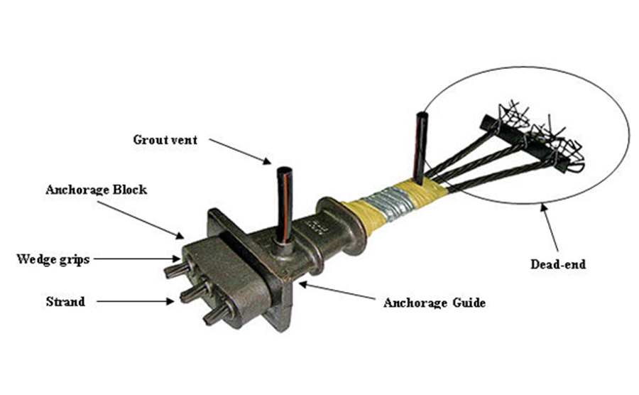
The Bridge beam is constructed mostly as posted tensioned or pre-tensioned beams. In addition to precast beams, concrete slabs on abutments, box culverts, box girders, suspension bridges are also constructed to accommodate passengers or vehicular movements.
The design of the post-tensioned bridge beam discussed in this article is in accordance with BS 8110 part 1.
In this article, we are discussing the ULS design (ULS bending moment capacity estimation) of a post-tensioned bridge beam using the strain compatibility method.
Let’s discuss a little bit about the strain compatibility method.
Ultimate limit state strain (εpb )in the selection at tension face is made from the following components.
- Strain due to effective post-tension force( Pe) (after losses) – εpe
- Strain-induced by the applied loading – εpa
Strain due to the prestressing Pe can be calculated as follows
εpe = Pe / [ Aps.Eps ]
where Aps is the area of the tendons and Eps is the steel elastic modulus.
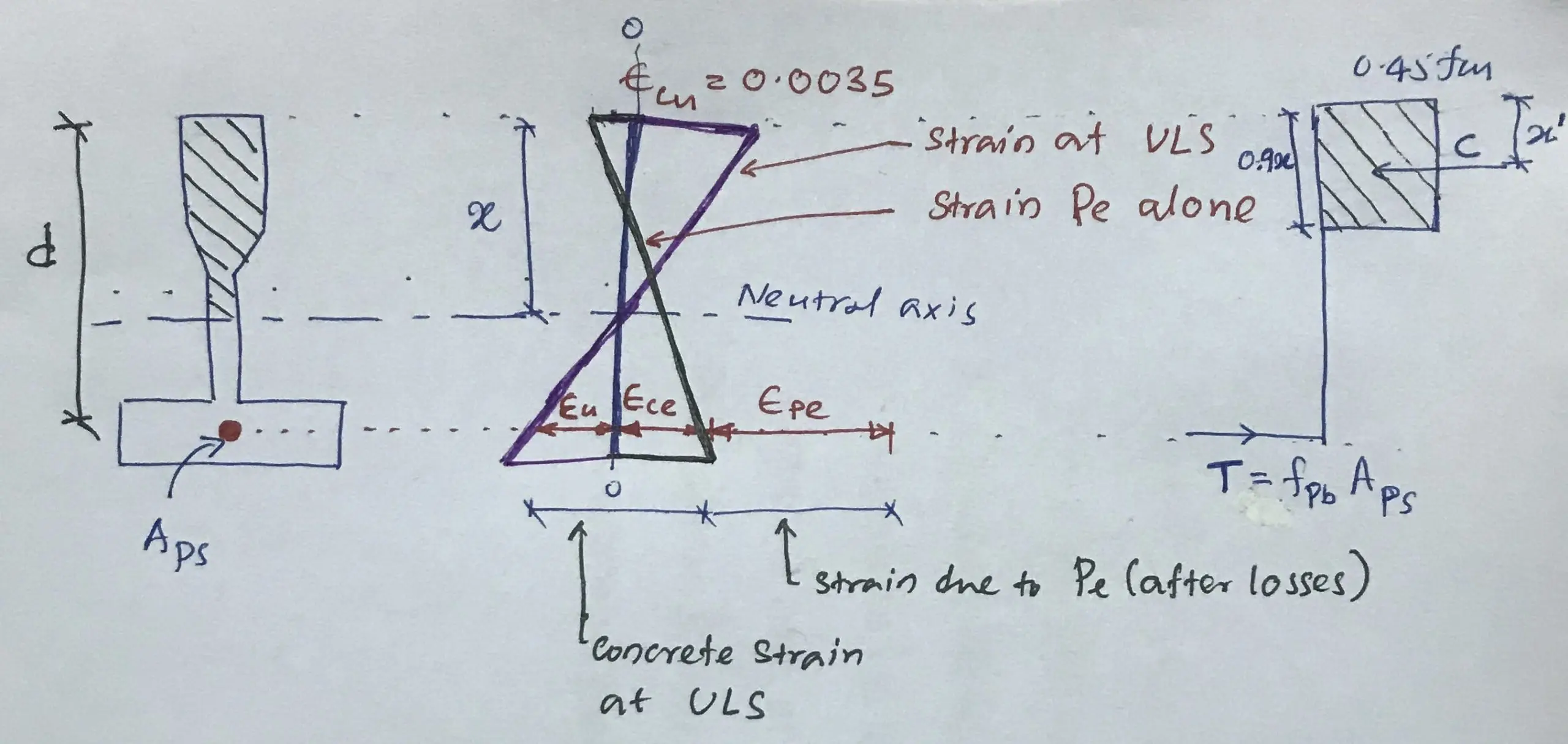
During the prestressing, compression is below the neutral axis and the section is subjected to compression strains εce and εpe.
Here, εceis the compressive strain in the section at the level of steel by the “Pe“.
Applied loads will first make this strain (εce) zero, and then the steel tensile strain will be developed. The total tensile strain developed by ultimate limit state loading will be
εpa = εce + εu
Further,
Reduction in concrete compressive strain = increase in steel tensile strain
This is because of the steel and the concrete in the same section. Concrete strain reduces and simultaneously steel strain increases. Both happen at once.
Here,
εce = fco / Ec = [Pe/Ec] [ 1/A + e2/I]
εu = εcu [ d – x ] / x = 0.0035 [ d – x ] / x
The tensile strain of the steel can be expressed as
εpb = εu + εce + εpe
We have to use an iterative process to calculate the neutral axis depth until compression force equals tension force (C = T)
Once we calculate the tensile strain (εpb ), calculate the bending capacity of the section from the following equation.
Mu = fpb Aps (d-d’)
The following steps are followed when the bending capacity of the bridge beam is calculated.
- Assume a natural axis depth and calculate compression force (C = 0.45.fcu.A’c)
- Then calculate the tensile stress in the tendon.
- For this, calculate the tensile strains in the tendons (εpb = εu + εce + εpe)
- And then find the steel strass from the stress-strain curve
- Check whether the tensile force (T = fpb Aps) and the compression force is equal.
- If not, repeat the calculate by changing the neutral axis depth until they are equal
- After finding the neutral axis depth calculate the bending capacity of the section(Mu = fpb Aps (d-d’)).
Let’s study this with a worked example
Data for Bridge Beam Design
- Span = 16m
- weight of the deck = 1 kN/m
- Imposed load = 4 kN/m
- Density of concrete 24 kN/m3
- Yield strength of tendons, fpu = 1670 N/mm2
- Area of the tendons, Aps = 882 mm2
- Concrete cube strength, fcu = 40 N/mm2
- Area of the section, A = 121000 mm2
- Steel Elastic Modulus, Eps = 205 kN/mm2
- Concrete Elastic Modulus, Ecu = 28 N/mm2
- Second Moment of the area of the section, I = 5.236×109 mm4
- Prestressing Force, Pe = 744 kN
Calculate Design Moment
Desing load factors were taken from the BS 8110.
Area of the section =121000mm2
Selft weight of the beam = 121000 x 10-6 x 24 = 2.9 kN/m
Design Load = 1.4 ( 2.9 + 1) + 1.6 x 4 = 11.86 kN/m
Design moment = wl2/8 = 11.86 x 162 / 8 = 379.52 kNm
Moment Capacity Check
Calculate the neutral axis depth
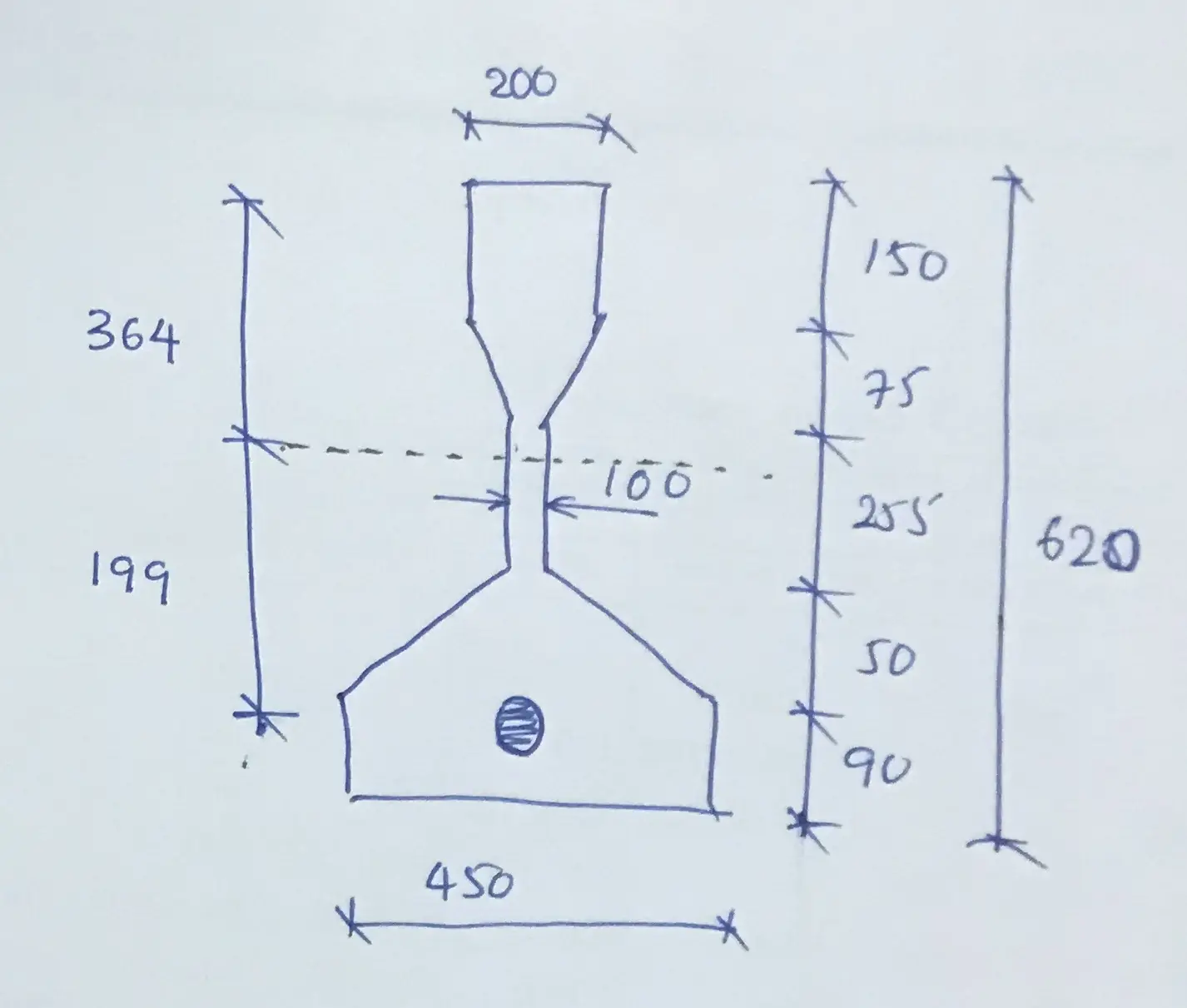
Assume neutral axis, x = 400mm from top extreme fibre
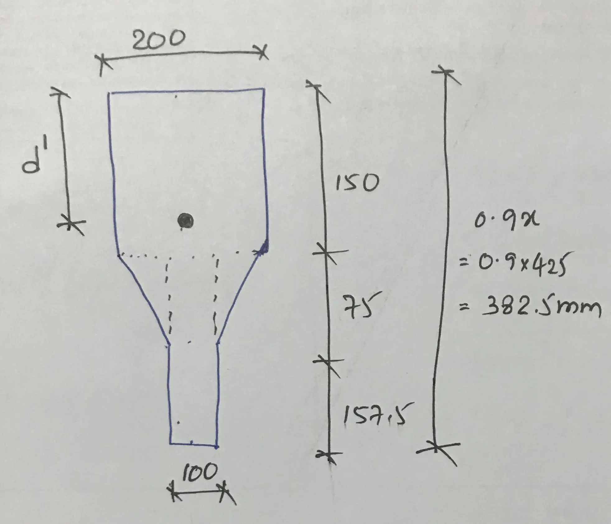
Heith of the compression stress block = 0.9 x = 0.9 x 400 = 360mm
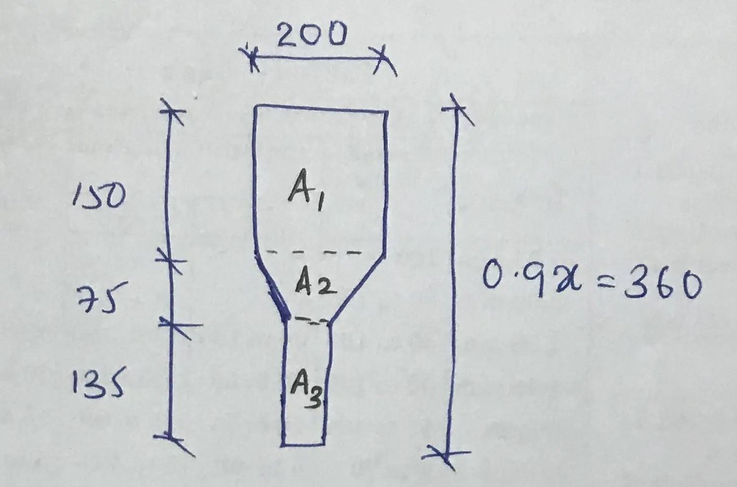
Area of the compression stress block, A’c = A1 + A2 + A3
A’c = 150×200 + 0.5x(200+100)x75 + 135×100 = 54.75×103 mm2
Compressive force
C = 0.45.fcu.A’c
C = 0.45 x 40 x 54.75×103 = 985.5×10³ N = 985.5 kN
Calculate Tension Force
T = fpb Aps
Firstly, we need to calculate the tensile stress (fpb). Let’s use strain in the section.
εpb = εpe + εce + εu = Pe/[Aps.Eps] + [Pe/Ec][ 1/A + e2/I] + 0.0035[d-x]/x
εpe = Pe/[Aps.Eps] = 744×103 / (882 x 205×103) = 4.11x 10⁻³
εce = [Pe/Ec][ 1/A + e2/I = [744×103/28×103][1/121000 + 1992/5.236×109] = 0.42x 10⁻³
εu = 0.0035[d-x]/x = 0.0035 x [(199+364) -400] / 400 = 1.43x 10⁻³
εpb = 4.11x 10⁻³ + 0.42x 10⁻³ + 1.43x 10-3 = 5.96x 10⁻³
Strain in the tendon is 5.96x 10⁻³ ≈ 0.006
From stress and strain diagram for prestressing tendons in BS 8110 Part 01, following infromation can be considered for the design
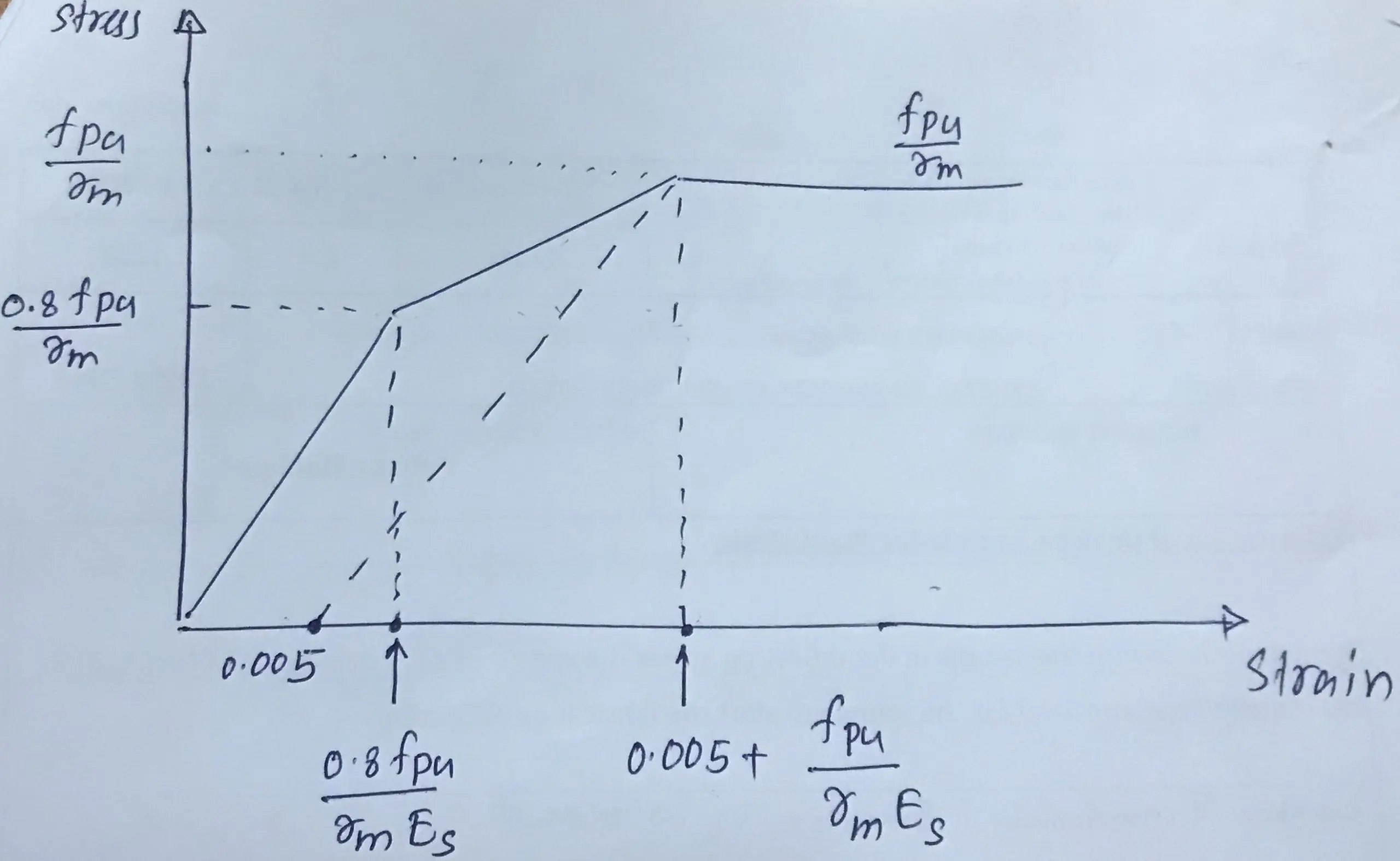
Follwoing information are available
- ϒm = 1.5
- fpu = 1670 N/mm2
- Eps = 205 kN/mm2
fpu/γm = 1670 / 1.15 = 1452.2 N/mm2
0.8fpu/γm = 1452.2 x 0.8 = 1161.7 N/mm2
fpu/γmEps = 1670 / (1.15 x 205×103) = 0.0071
0.8fpu/γmEps = 0.0071 x 0.8 = 0.0057
Now values can be marked in the above figure as follows.
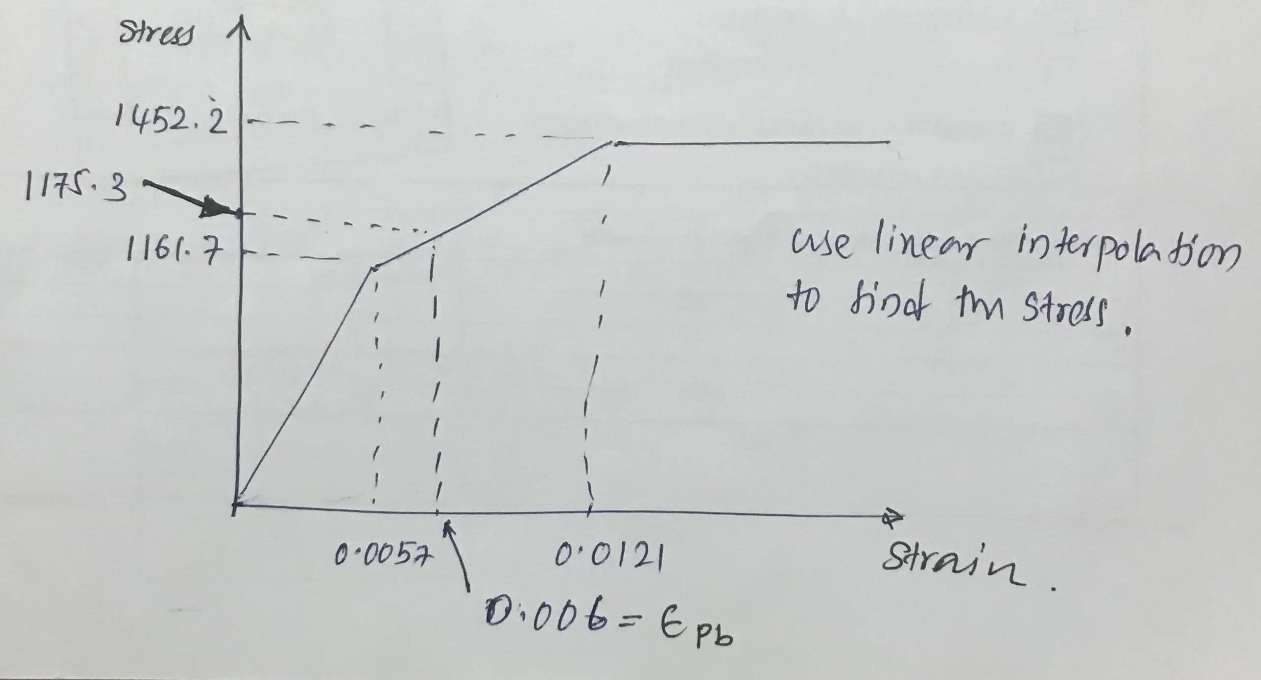
Using linear interpolation, we can find the stress in the tendons.
fpb = 1175.3 N/mm2
Area of tendons, Aps = 882 mm2
Now we can calculate the Tension force,
T = fpb Aps = 1175.3 x 882 = 1036.6×103 N = 1036.6 kN
C = 985.5 kN
T ≠ C, the assumed neutral axis depth is not correct. We have to follow the same procedure until T = C.
We may have to do several iterations to get close to the correct neutral axis depth.
Firstly, we check the range for the neutral axis depth.
We can assume C = 1036.6 kN (tensile force) then check the depth
C = 0.45.fcu.A’c
1036.6×103 = 0.45 x 40 x A’c
A’c = 57588.9 mm2
57588.9 = 150×200 + 0.5x(200+100)x75 + (0.9x – 150 – 75 )x100
x = 431.54 mm
Thus, we can say that “x” should be less than this value.
Assume x = 425mm
εpb = 4.11x 10⁻³ + 0.42x 10⁻³ + 0.0035 x [(199+364) -425] / 425 = 0.0057
Following the similar procedure, from above chart,
fpb = 1161.7 N/mm2
T = fpb Aps = 1161.7 x 882 = 1024.6×103 N = 1024.6 kN
C = 0.45.fcu.A’c = 0.45 x 40 x [150×200 + 0.5x(200+100)x75 + 157.5×100} = 1026×103 N = 1026 kN
Therefore, we can conclude that T ≈ C
Then consider, x = 425mm for calculating the bending capacity.
Mu = fpb Aps (d-d’)
Where d’ is the centroid of the compression stress block.
d’ can be calculated by taking the moment around an edge. Then the calculation is not included as it is a simple calculation.
d’ = 159.6mm
Let’s calculate the bending capacity.
Mu = fpb Aps (d-d’)
This equation can be written as
Mu = T (d-d’)
Mu= 1024.6 (563 -159.6) / 1000 = 413.3 kNm
The bending capacity is 413.3 kNm and the applied bending moment is 379.52 kNm. The section is ok for bending.
However, the section should be checked for the shear. You may refer to a separate article for the shear design of post-tension beams.
The article Bridge Design to BS 5400 could be referred to get more information on the bridge beam design theory.
Further reading on precast concrete the Wikipedia article prestressed concrete could be referred to.
![Prestressed Composite Beams [design aspects]](https://www.structuralguide.com/wp-content/uploads/2020/11/Composite-Beams.png.webp)