Desing of prestressed composite beams is discussed in this article. Composite beams are widely used in construction. The composite action of the beam enhances the load-carrying capacity of the beam.
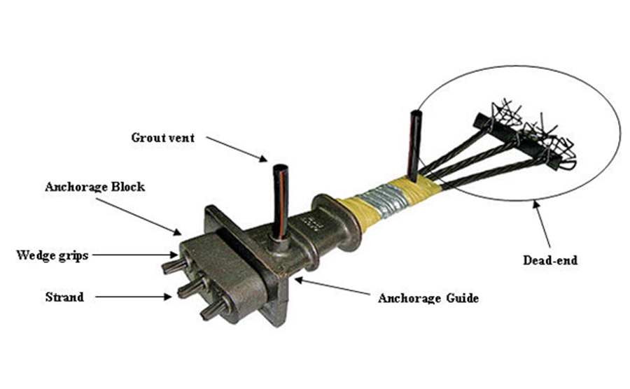
What is Prestress Concrete Composite Construction
In addition to the prestressed beam, there will be a concrete deck, concrete fill around the beam, voids in the concrete fill, etc. Consideration of additional stiffness induced by the concrete other than the prestress beam is the composite action.
Initially, we place the prestressed beam on the abutment. They can be placed one after another without a gap of a gap. It depends on the design consideration.
Then we fill the concrete in the deck or between beams. Once the concrete gets harder, it acts together with the prestress beam and provides additional stiffness to the section.
The following figure indicates the different types of prestressed composite beams.
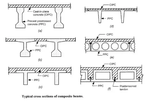
Let’s discuss the advantages and disadvantages of prestressed composite beams.
Advantages of Composite Construction
- There is a significant reduction in the construction time
- Low strength concrete can be used for in situ concrete
- No formwork is required when the beams are placed closely.
- An increase in the cross-section area of the section results in higher stiffness of the beam. As a result, beam bending and shear capacity increases.
- Due to the higher stiffness, it reduces the deflection of prestressed composite beams
Disadvantages of Composite Construction
- Designers need to pay more attention to the design procedures as they are a bit complex than the usual method. The correct idealization of the actional condition should be done during the design.
- Due to the composite slab, there will restrain resulting in an increase of prestress losses. Further, there could be a restrain moment due to this action.
- Different shrinkages in the section could induce additional stresses.
Let’s discussed the composite action in prestressed composite beams.
The addition of the stresses in each stage of construction is done to find the service stresses in the section.
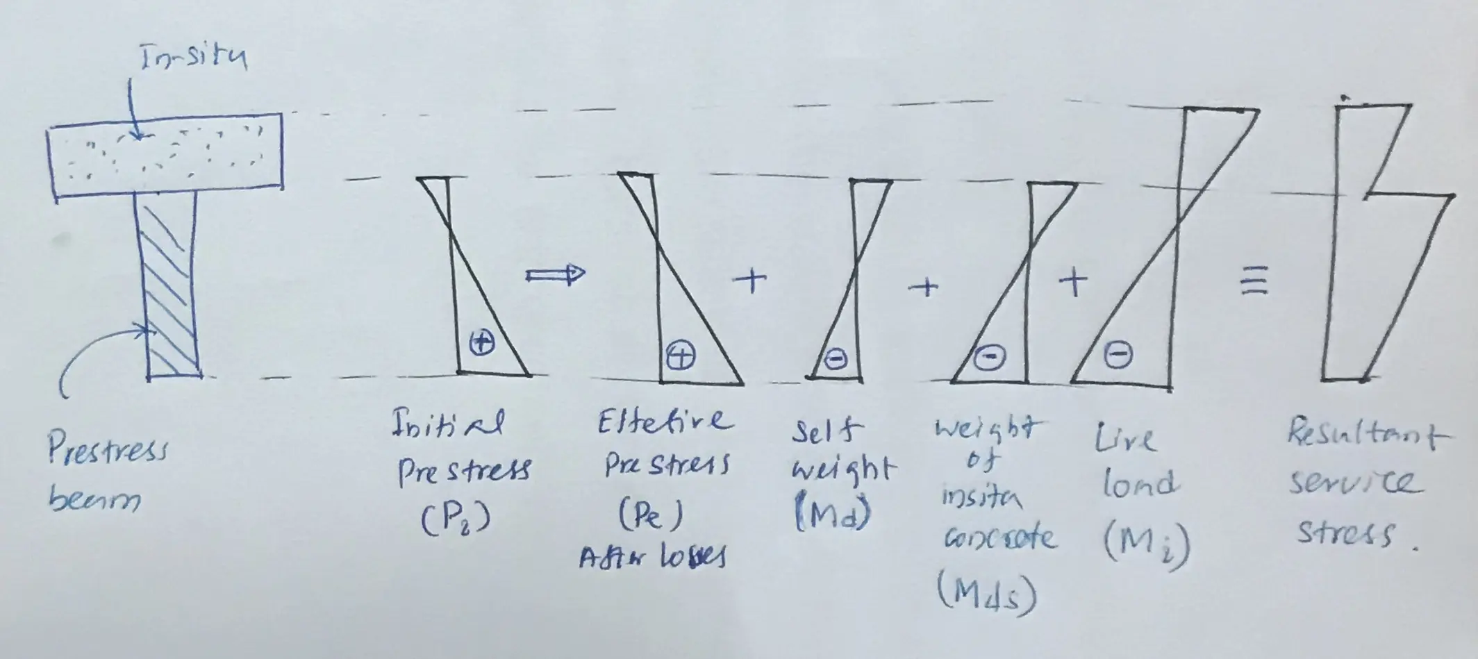
The above figure indicates an unpropped construction where the weight of the cast-in-situ concrete is born by the prestress beam.
However, if we can provide props during the construction of the deck, its weight will be born by the props without transferring to the prestress beam. Once the supports are removed after concrete gets hardened, composite action will carry the dead with the composite beam.
This reduces the service stress in the beam. But there is an increase in the cost due to the formwork provided.
It is suggest reading the article Bridge Design to BS 5400 for further information on calculating the stress in the section. It will not be discussing in this article.
In addition, the Bridge Beam Design article elaborates on the procedure to be followed when designing the method for a non-composite beam.
Attention shall be made to the following factors when designing the composite Beams
Allowable compressive and Tensil stresses
Stresses in the tensile face and the compression face of the beam shall be checked in accordance with the relevant standards. Limiting values given in the specification should be followed.
Differential Shrinkage
Since we are placing the concrete on concrete that already harden, there will be differential shrinkage.
Though the new concrete shrink, concrete in the prestress beam will not shrink. Therefore, there will be a relative movement in the place that the beam and cast-in-situ concrete is connected.
Generally, the water content of the cast-in-situ concrete is lower than the beam as it has low strength. Due to the higher water content, shrinkage will reduce.
Horizontal Shear
The composite action of prestressed composite beams can only be taken when the horizontal shear stress at the interface between the beam and the slab is transferred.
Slip between the two elements will lose the composite action.
There are several methods that can be adopted to ensure proper bonding of the beam with the slab.
- Roughing the concrete surface of the beam
- Providing reinforcement as extension form the beam into the slab
- Shear keys could also be constructed in the interface
Now let’s see how do we calculate the service stressed in a composite beam with an example
Prestressed Composite Beams Design – Worked Example
This example elaborates on the method of calculating the stressing in the beam and the composite section. Allowable stresses in each component/stage of the section shall be checked with the relevant standard.
Further, you may refer to the article bridge beam design for further information on the ultimate limit state design of the post-tensioned beam.
Design Data
-
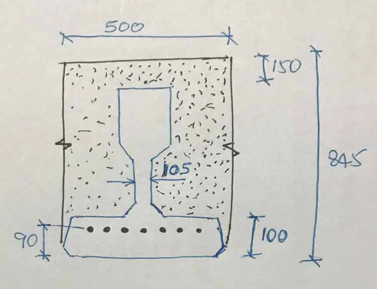
- Span = 15m
- Beams are placed at 500mm centers
- Depth of the beam = 845mm
- P = 1140 kN (prestressing force after all the losers)
- Imposed Load = 12 kN/m
- Ac = 1.47 x 105 mm2 – Area of the Beam
- Ib = 7.785 x 109 mm4 – Second moment of area of the beam
- Zt = 19.20 x 106 mm3 – Section modulus top
- Zb = 26.91 x 106 mm3 – Section modulus bottom
- w = 3.5 kN/m – weight of the beam
- ȳ = 289 mm – depth to the neutral axis from the soffit
The following figure indicates the typical beam detail.
Let’s see what are the stresses we need to calculate.
The following figure indicates the stresses only due to the prestressing and self-weight of the prestressing beam.
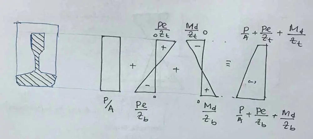
Let’s calculate all stress in the beam
Beam weight = 3.5 kN/m
Moment, Md = 3.5 x 152 / 8 = 98.4 kNm
Eccentycity, e = 289 – 90 = 199 mm
P/A = 1140 x 103 / 1.47 x 105 = 7.76 N/mm2
P e / Zb = 1140 x 103 x 199 / 26.91 x 106 = 8.4 N/mm2
P e / Zt = 1140 x 103 x 199 / 19.20 x 106 = 11.82 N/mm2
Md / Zb = 98.40 x 10⁶ / 26.91 x 106 = 3.65 N/mm2
Md / Zt = 98.40 x 10⁶ / 19.20 x 106 = 5.12 N/mm2
Total stress in the top fibre = -7.76 + 11.80 – 5.12 = -1.06 N/mm2
Total stress in the bottom fibre = -7.76 – 8.4 + 3.65 = -12.53 N/mm2
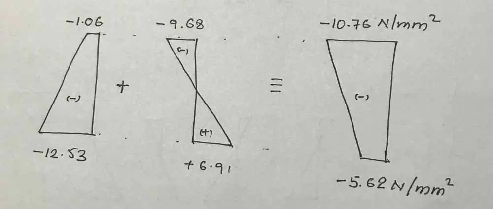
Calculate the Stress in the Beam Due to cast-in-situ concrete
In these types of beams, the prestress beam to act as the formwork to the cast-in-situ concrete.
Area of cast insitu concrete = 845 x 500 – 1.47 x 105 = 2.755 x 10⁵
Weight of the cast insitu concrete, Wci = 2.755 x 105 x 24 / 106 = 6.612 kN/m
Moment, Mci = 6.612 x 152 / 8 = 185.96 kNm
Now calculate the stresses
Mci / Zb = 185.96 x 10⁶ / 26.91 x 106 = 6.91 N/mm2
Md / Zt = 185.96 x 10⁶ / 19.20 x 106 = -9.68 N/mm2
Now, we can calculate the stress in the section as follows.
Calculate the Stress in the Prestressed Composite Section
The stiffness of the overall section can be taken into account in composite design.
Calculate the neutral axis depth of the composite section.
y = 845 / 2 = 422.5 mm
The second moment of area of the section
Ic = 500 x 8433 / 12 = 2.514 x 1010 mm4
Calculate the bending moment due to the imposed loads
MI = 12 x 152 / 8 = 337.5 kNm
Both the top and bottom stresses are similar due to the symmetry of the section.
Calculate the bending stress
MI y / Ic = 337.5 x 106 x 422.5 / 2.514 x 1010 = 5.67 N/mm2
Now let’s calculate the stresses in the section. It is done by adding all the stresses in the section.
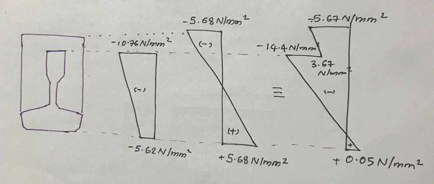
We can calculate the allowable stress in the section based on the relevant design class of the relevant standards. If the above values are within the acceptable limits, the section is acceptable.
In this article, we are not calculating the allowable stresses for the prestressed composite beams.
Let’s calculate the tensile stress at the bottom of the cast-in-situ concrete.
The following figure indicates the stress variation.
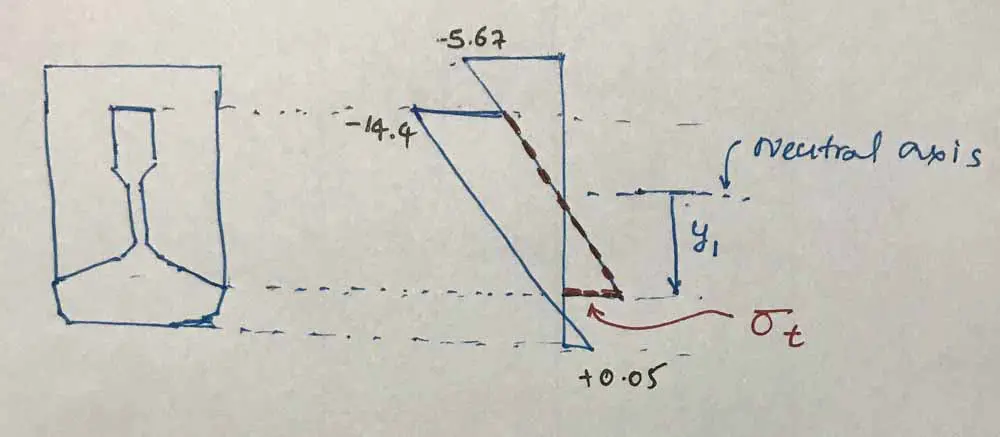
Let’s calculate the depth from the neutral axis.
y1 = 845/2 -100 = 322.5 mm
σt = MI y / Ic = 337.5 x 106 x 322.5 / 2.514 x 1010 = 4.31 N/mm2
Therefore, the stress in the insitu concrete is 4.31 N/mm2.
In addition to the stresses in the prestressed composite beams, the stress in the in-situ concrete(calculated above) and stress in the top of the prestressed beam should be checked.
![Bridge Beam Design [Post Tensioned]](https://www.structuralguide.com/wp-content/uploads/2020/10/Bridge-Beam.jpg.webp)