Tunnel design is done in reservoirs or underground roads are not constructed every day like other structures. It could be constructed in rock or soil.
For example, a tunnel constructed for a highway is designed for external loads which are applied from the rock cover or any other overburden material.
However, tunnels carry water are design for both external and eternal loads.
When the tunnel carries water with a large head, it exerts water head on the surrounding area. Especially when a rock cover is smaller we have to check whether the overburden is sufficient to take that load when the tunnel is unlined.
When the tunnel is lined we have to consider the loads on the tunnel and it should be designed considering those factors. In addition, the area around the tunnel can be a collapse in the tunnel.
Depending on the type of surrounding material, a tunnel design can be carried out.
Generally, tunnels with having good quality rock cover are not lined by reinforced concrete in addition to the shotcreating.
However, at the outlet, the tunnel has to be lined by a steel liner or a concrete liner if there is no adequate rock cover. Most of the tunnels designers come across this situation. They normally find the distance that the unlined section can be continued and the rest of the length is lined.
Design of a Section with an adequate rock cover
When an adequate rock cover presents, we can do the design of the tunnel with lining or without lining. If we have good quality rock, we can have an unlined tunnel. But if the rock is weak we have to consider the rock quality for the design.
Tunnel Design for External Loads
When adequate rock cover is present, we need not worry about the total collapse of the tunnel.
However, it can fail locally. If the rock is not fairly good or it can not be stabilized with shotcreeting (reinforced or un-reinforced), we have to have a lining that can bear the external loads.
Lining design is done considering the type of rock.
Rock quality and the type of rock shall be inspected at the site and then the design should be carried out. In tunnel designing books or design standards, it can be found the load that needs to be considered for the lining design depending on the rock type.
“EM 1110-2-2901 Tunnels and Shafts in Rock” one of the most commonly used standards that can be reffed for our designs. It provides a guideline to design tunnels depending on different ground conditions.

The above figure is extracted form EM 1110-2-2901. Depending on the rock condition, fracture spacing and RQD value, rock load can be selected. For example, consider massive moderately jointed rock, rock load is 0.5B.
Hp = 0.5 B x (density of rock)
Assume tunnel diameter(B) as 2.5 m
Rock density 25 kN/m3
Hp = 0.5 x 2.5 x 25
= 31.25 kN/m2
This load can be applied to the tunnel as a gravity load. Finite element analysis or equations given in codes for different shapes of tunnels can be used to find the stresses of the tunnel.
In addition to the rock loads, the external water pressure should be considered for the design. If the proper drainage system is not provided, the water head or part of the head should be considered for the design.
When the proper drainage system is provided, external pour water pressure can be reduced or nearly eliminated for the design.
However, design water pressure may be taken as the lesser of 25 percent of the full pressure and a pressure equivalent to a column of water three tunnel diameter high.
Loads should be factored when analyzing the tunnel. EM 1110-2-2901 provides a table that can be used to create load combinations.

Load combinations can be created by considering the factors given in the above table.
If there is a lateral deformation, it increases the bending and shear forces of the tunnel. When large rock cover exists, the tunnel can not deform laterally.
This can be considered in the analysis and rock can be considered as a support to the tunnel.
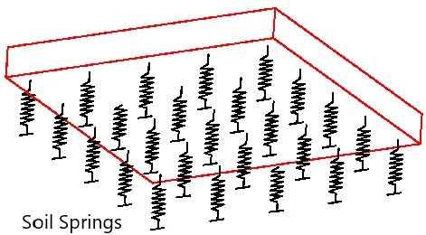
Rock support can be a model depending on the type of rock. The subgrade reaction of the rock can be calculated for the equations given in the EM 1110-2-2901.

Depending on the arc angle, element size, position reaction and modulus of rock, subgrade reaction can be calculated in radial and tangential directions.

The above figure shows the graphical representation of the subgrade reaction.
We should apply the subgrade reaction as shown in the figure.
Depending on the design requirements, we may omit the tangential subgrade reaction.
In addition, if we model the tunnel with software, springs should not be allowed to take any tension. Compression only condition should be considered as rock can not take any tension load.
Tunnel Design for Internal Loads
When there is an adequate rock cover, the internal load generated from the water head can be bared by the surrounding rock. Also when a large rock cover exists, it does not allow the tunnel to deform. Therefore, stresses are not generated due to the internal water load.
Design of a Section with an inadequate rock cover
Good quality rock can be found in the areas where the tunnels are constructed. However, there are instances we meet with poor quality rock or soils on the top of the tunnel. Even if we have the quality rock, it should be adequate to take the internal load exerted by the water head on the surrounding rock.
Design for external loads
When the rock cover is not adequate, we have to have either steel lining or concrete lining to carry the internal loads.
When the tunnel is not carrying any water, it does not have internal pressure on the surrounding rock. External loads applied on the tunnel lining should be considered when designing it.
The technical paper “Big Tunnels in Bad Rock 2000 Terzaghi Lecture by Evert Hoek” can be referred for as the design. It is a very good guide to design such cases.
However, there are different techniques that have been proposed by researches/books for calculating rock load.
EM 1110-2-2901 provides a guideline to find a position that required the lined section. Beyond this position, the section can be constructed as an unlined section if required.
The following figure extracted from EM 1110-2-2901 can be referred to find the distance that lined section is required.
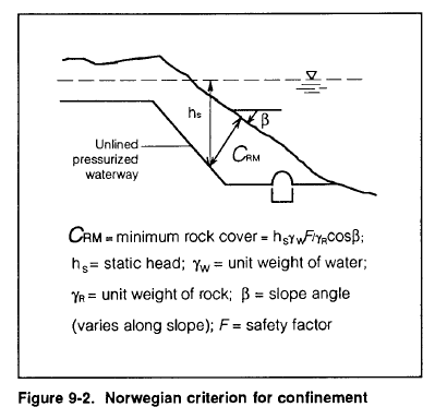
Figure 9-2 shows the requirement of rock cover for unlined pressurized waterways.
It is the Norwegian criterion for the confinement of rock. This concept is a commonly used method by design engineers.
This is a very simple technique and tool to find the minimum rock cover for an unlined tunnel. The weight of the rock mass or the overburden material is balanced by the internal head of the tunnel.
Attention should be paid to the surface condition when finding the rock cover(hs).
For example, if the top cover is soil or weathered rock, this type of material can be washout when water is flowing along the surface.
In addition, the safety factor should be considered adequately. It may vary between 1.05 – 3 and maybe refer to the design intent.
Figure 9.1 shown below, also can be used for designing the tunnels. We can select a method, and then the design can be started. The most commonly used method and the simplest method is the Norwegian criterion for confinement.
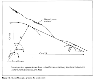
Once we select the criteria, we can calculate the section that required the lining from the equation given in the guideline.
The external load that needs to consider for the design is the weight of rock cover or weight of overburden material.
We can apply that weight as a gravity load for the analysis.
If there is a large rock cover in the lateral direction, we can consider rock as support against the lateral deformation. However, if there is no sufficient rock cover in the lateral direction, it is advisable to not to consider it as a support.
Design for Internal Loads
When sufficient rock cover is not present, tunnels should be lined as discussed above.
Water head can be considered as the internal load while the weight of the overburden material can be considered as the load applied from the top of the structure as a gravity load.
It should be very careful with the weight of the overburden material depending on the value of the load and the deformation of the tunnel.
Some times it may act as beneficial but it could be an adverse load as well.
For example, if we apply a factor when creating a load combination, it generates a weight that is more than that of the existing weight of overburden material.
It may increase the hogging moment and may reduce sagging moments. Actually this purely depends on the analysis we do. So it is better to be very careful with the weight of the overburden material if we intend to apply to the model.
Further, the article design and construction of tunnel junction could also be referred for additional information on this subject.